Parallel decoupling identification method for induction motor stator resistance and speed

A technology of induction motor and stator resistance, which is applied in the fields of power electronics and electric drive, can solve the problems of inaccurate observation values, and achieve the effect of ensuring decoupling, reducing influence and realizing accurate compensation.

Active Publication Date: 2020-06-30
HARBIN INST OF TECH
View PDF7 Cites 0 Cited by
  • Summary
  • Abstract
  • Description
  • Claims
  • Application Information

AI Technical Summary

Problems solved by technology

[0004] The purpose of the present invention is to solve the problem of inaccurate observation value at light load and no-load in the existing online identification method for stator resistance of induction motor without speed sensor, and propose a parallel decoupling of stator resistance and rotational speed of induction motor Identification method

Method used


Image

  • Parallel decoupling identification method for induction motor stator resistance and speed
  • Parallel decoupling identification method for induction motor stator resistance and speed
  • Parallel decoupling identification method for induction motor stator resistance and speed

Examples


specific Embodiment approach 1

[0032] A parallel decoupling identification method for induction motor stator resistance and rotational speed according to this embodiment, the decoupling identification method is realized through the following steps:

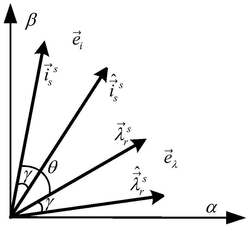
[0033] Step 1. Design the relationship between the rotor flux error and the stator current error:

[0034]

[0035] In the formula, Indicates the stator current error, Indicates the rotor flux linkage error; L m Represents the mutual inductance of the induction motor; θ represents the power angle of the induction motor, which is the angle between the electronic current and the rotor flux linkage;

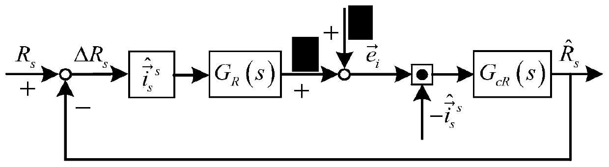
[0036] Step 2. Using the relationship between the rotor flux error and the stator current error in step 1, decoupling the stator resistance error part of the stator current error, the obtained stator resistance error part is expressed as:

[0037]

[0038] In the formula, is the stator current error The rotational speed error part in is the stator ...

specific Embodiment approach 2

[0047] The difference from the specific embodiment 1 is that in this embodiment, a parallel decoupling identification method between the stator resistance and the rotational speed of an induction motor, the process of designing the relationship between the rotor flux linkage error and the stator current error described in step 1 is as follows:

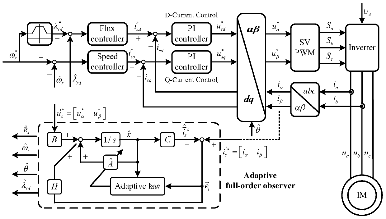
[0048] Step 1. Select stator current and rotor flux linkage as state variables, and determine the induction motor mathematical model as:

[0049]

[0050] is the stator current, is the rotor flux linkage, is the motor input voltage,

[0051]

[0052]

[0053] R s Indicates the induction motor stator resistance, R r Indicates the induction motor rotor resistance, L s Indicates the induction motor stator inductance, L r Indicates the induction motor rotor inductance, L m Indicates the induction motor mutual inductance, T r Indicates the induction motor rotor time constant, δ is the leakage inductance coefficient, ω e...

specific Embodiment approach 3

[0085] The difference from the second specific embodiment is that in this embodiment, a parallel decoupling identification method between the stator resistance and the rotational speed of an induction motor uses the relationship between the rotor flux error and the stator current error described in step two to decouple the stator current error The process of the stator resistance error part is:

[0086] Step 2 1. Current error by the rotational speed error part and the stator resistance error part Composition, the current error is expressed as:

[0087]

[0088] in,

[0089]

[0090]

[0091] Indicates the stator current error of the induction motor, Indicates the part of the speed error in the stator current error of the induction motor, Indicates the stator resistance error part of the induction motor stator current error;

[0092] Step two 2, combining formula (7), (8), (9) and (11), obtain the relation of speed error part and stator resistance error p...


PUM


Abstract

The invention relates to a stator resistance and rotational speed parallel decoupling identification method of an induction motor. In an existing stator resistance on-line identification method of a speed-less sensor induction motor, the problem of inaccuracy observation value during light load and no load exists. The stator resistance and rotational speed parallel decoupling identification methodof the induction motor comprises the steps of 1, designing a relation between a rotor magnetic flux error and a stator current error; 2, decoupling a stator resistance error part in the stator current error by employing the relation between the rotor magnetic flux error and the stator current error; 3, determining stator resistance self-adaption rate and induction motor rotor rotational speed self-adaption rate; and 4, estimating a stator resistance value of the induction motor by a PI regulator. By the stator resistance and rotational speed parallel decoupling identification method, the observation precision and accuracy of stator resistance during light load and no load is improved.

Description

technical field [0001] The invention belongs to the field of power electronics and electric transmission, and specifically designs an online decoupling identification method for a speed sensorless induction motor stator resistance based on a full-order observer. Background technique [0002] The position sensorless induction motor vector control method has the advantages of low hardware complexity, low cost, small size, high anti-interference ability, high reliability, and low maintenance requirements, and is widely favored by academia and industry. However, the high-precision and high-efficiency control of induction motors in its operating range requires accurate motor parameters. The temperature and complex electromagnetic environment will cause great changes in the resistance value of the stator resistance, which can reach 50% of the real value at most. The error of the stator resistance will cause the speed sensorless vector control model to be unable to accurately esti...

Claims


Application Information

Patent Timeline
Patent Type & Authority Patents(China)
IPC IPC(8): H02P21/24H02P21/13
Inventor 王勃罗成于泳徐殿国
Owner HARBIN INST OF TECH
Why Eureka
Try Eureka