A combined positioning shaft and positioning method

A positioning method and combined technology, applied in the field of combined positioning shaft and positioning, can solve the problem that the uniformity of the matching gap between the positioning shaft and the joint hole is difficult to control, it is difficult to ensure the vertical angle between the positioning shaft and the forming tool, and the metal joint is scratched. Hole matching shaft hole and other problems, to achieve the effect of good popularization and application value, good process stability and operability, avoiding direct contact and contact-type relative displacement

Active Publication Date: 2021-06-22
AEROSPACE INST OF ADVANCED MATERIALS & PROCESSING TECH
View PDF14 Cites 0 Cited by
  • Summary
  • Abstract
  • Description
  • Claims
  • Application Information

AI Technical Summary

Problems solved by technology

Since the uniformity of the fit gap between the positioning shaft and the joint hole is not easy to control, it is difficult to ensure the vertical angle between the positioning shaft and the forming tooling
When the positioning shaft and the metal joint hole are at a certain normal angle, the sharp part of the edge may scratch the metal joint hole and the supporting shaft hole of the forming tool, and the burr of the forming tool shaft hole will further affect the assembly and disassembly of the positioning shaft process, a vicious circle

Method used


Image

  • A combined positioning shaft and positioning method
  • A combined positioning shaft and positioning method
  • A combined positioning shaft and positioning method

Examples


Embodiment Construction

[0030] The present invention will be described in detail below in conjunction with specific examples and accompanying drawings.

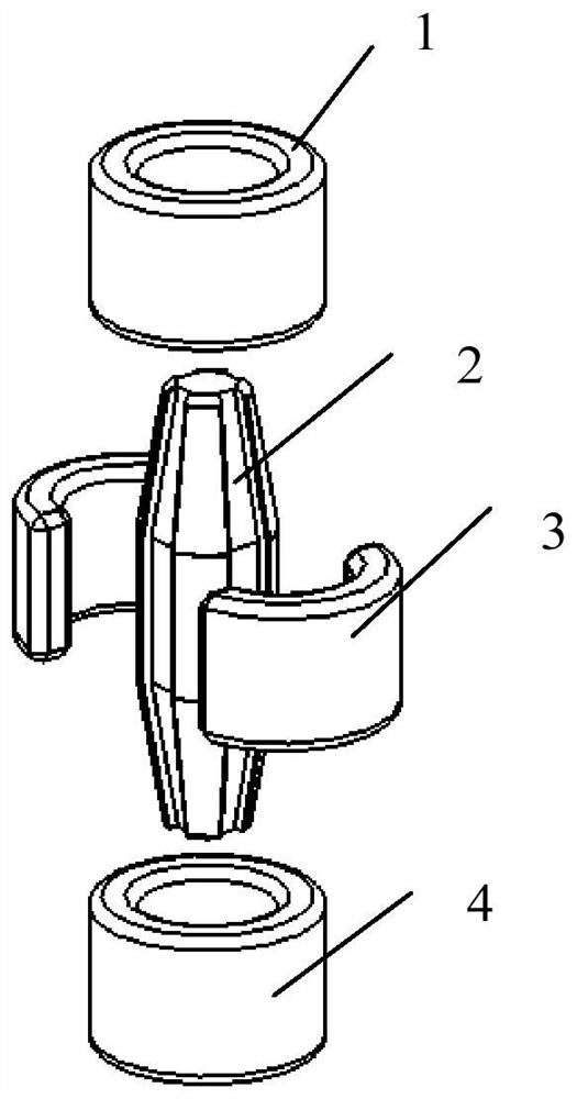
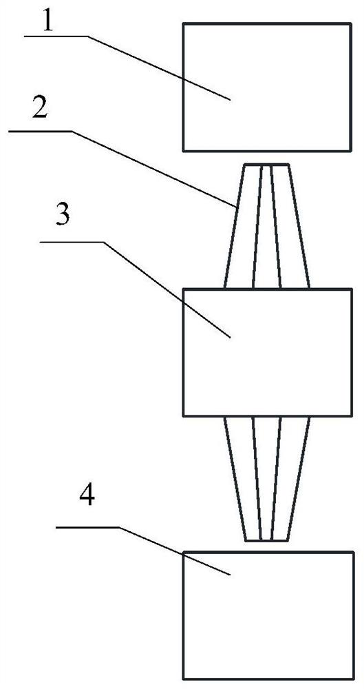
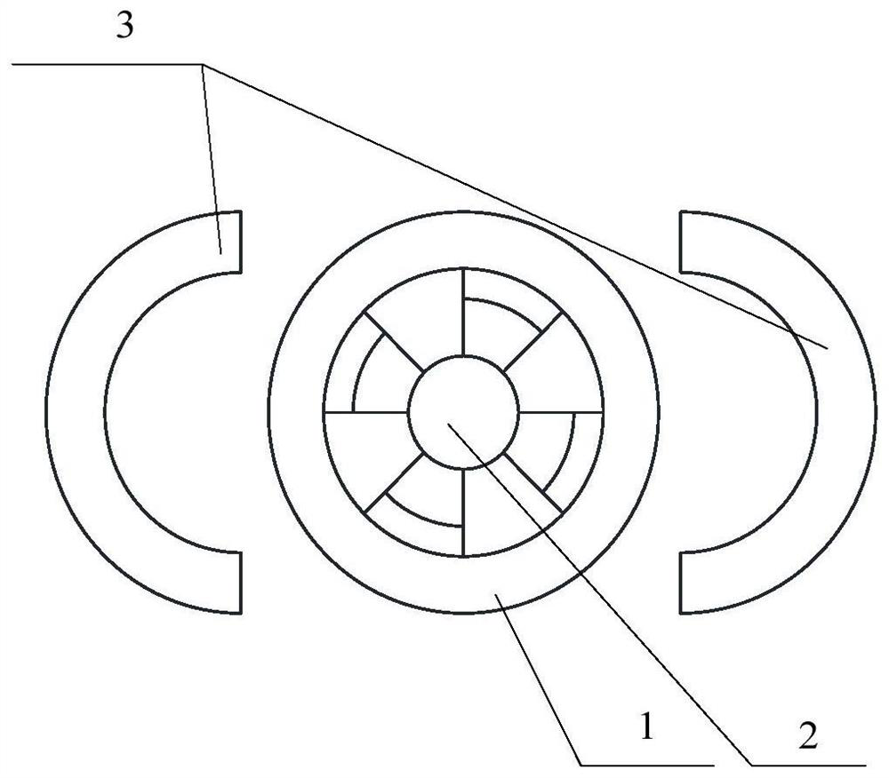
[0031] The present invention as figure 1 , 2 , 3 shown, by the upper mold shaft sleeve 1, center positioning shaft 2, split type protection sleeve 3 and the lower mold shaft sleeve 4 components. Centering axis 2 as Figure 4 , 5, the middle part is a cylinder 22, the two ends are conical 21, 23 jujube stone shape, the middle cylinder 22 of the central positioning shaft 2 is interference fit with the split type protection sleeve 3, and the upper and lower ends 21, 23 are respectively connected with the upper mold The axle sleeve 1 is matched with the lower die axle sleeve 4.

[0032] The split-type protective bushing 3 is bonded and installed in the shaft hole, the upper die bushing 1 and the lower die bushing 4 are respectively installed in the upper and lower molds, the central positioning shaft 2 is placed in the split-type protective bushing ...


PUM

PropertyMeasurementUnit
angleaaaaaaaaaa

Abstract

The invention proposes a combined positioning shaft and positioning method, which is composed of an upper mold shaft sleeve, a central positioning shaft, a split type protection shaft sleeve and a lower mold shaft sleeve. The central positioning shaft is a cylinder in the middle and a cone at both ends. The shape of the jujube pit, the middle part of the central positioning shaft is interference fit with the split type protective bushing, and the upper and lower ends are respectively matched with the upper die bushing and the lower die bushing. The invention adopts a unique combined structure, which can ensure that the positioning shaft does not have any relative displacement with the metal joint of the wing, avoids the generation of scratches, and at the same time can achieve accurate positioning during the forming of the wing and quickly separate the positioning shaft from the forming system when demolding , can smoothly realize the positioning of the composite material wing forming process, and ensure the accuracy requirements of the dihedral angle and installation angle of the wing.

Description

technical field [0001] The invention relates to a combined positioning shaft and a positioning method, which belong to the technical field of composite material forming and positioning. Background technique [0002] The composite material of the missile body structure can achieve a large weight reduction of the missile body, increase the payload of the missile, and effectively improve the tactical performance of the missile weapon system such as speed, range, maneuverability and lethality. It has become an advanced stealth missile body The development direction of structural materials. [0003] Foreign countries often regard the application ratio of composite materials in missile body structure as an important criterion for measuring the development level of missiles. In the process of catching up with foreign advanced all-composite material tactical missiles, the composite materials of missile body structure (including missile wings) In the development of the domestic aero...

Claims


Application Information

Patent Timeline
Patent Type & Authority Patents(China)
IPC IPC(8): B29B11/14B29C33/12
Inventor 韩蕾陈毅军孙辉汪东卢山嵇培军
Owner AEROSPACE INST OF ADVANCED MATERIALS & PROCESSING TECH
Why Eureka
Try Eureka