Radio frequency signal delay system

A technology of radio frequency signal and time delay system, which is applied in the direction of transmission system, electrical components, etc., can solve the problems of volume and loss increase, and achieve the effect of suppressing phase fluctuation

Inactive Publication Date: 2019-06-18
INST OF SEMICONDUCTORS - CHINESE ACAD OF SCI +1
View PDF5 Cites 1 Cited by
  • Summary
  • Abstract
  • Description
  • Claims
  • Application Information

AI Technical Summary

Problems solved by technology

[0004] Among these delay lines, fiber optic delay lines can obtain a large total delay while having low insertion loss. A 1km long optical fiber is required to obtain a delay of 5μs order, but due to the large total delay The corresponding total fiber length is relatively long. If the fiber delay method is used to perform precision tuning in a small range of several ns or tens of ns on the basis of a large total delay at the μs level, it is necessary to introduce a variety of different fiber lengths. , or use the method of adding cascaded optical switches to improve the topology of optical fibers of different lengths, so that the volume and loss of the entire system will increase again. On the basis of taking into account the secondary fine delay of several ns to tens of hundreds of ns
At this point, the emergence of integrated on-chip delay lines changed the situation

Method used


Image

  • Radio frequency signal delay system
  • Radio frequency signal delay system
  • Radio frequency signal delay system

Examples


Embodiment Construction

[0049] In order to make the object, technical solution and advantages of the present invention clearer, the present invention will be further described in detail below in conjunction with specific embodiments and with reference to the accompanying drawings.

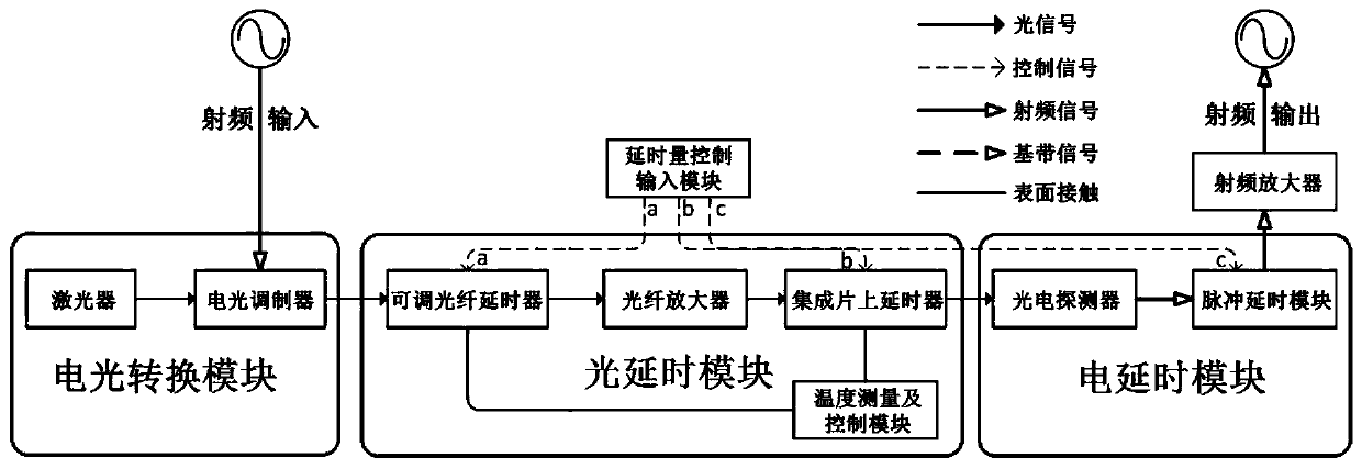
[0050] The radio frequency signal delay system provided by the present invention realizes a wide range of precise and tunable radio frequency delay through a combination of optical delay and electrical delay, and at the same time monitors and controls the temperature of the system delay module to realize the delay module Stable work, thereby suppressing the phase fluctuation of the delayed output signal of the system.

[0051] Such as figure 1 as shown, figure 1 It is a block diagram of a radio frequency signal delay system provided by the present invention, and the delay system includes:

[0052] The electro-optical conversion module is used to modulate the radio frequency signal to be delayed onto the optical carrier ...


PUM


Abstract

The invention discloses a radio frequency signal delay system, which comprises an electro-optical conversion module used for modulating a radio frequency signal to be delayed onto an optical carrier to obtain an optical carrier signal; The optical delay module is used for enabling the optical carrier signal to obtain optical delay; And the electric delay module is used for demodulating the radio frequency signal from the optical carrier signal subjected to the optical delay, and enabling the demodulated radio frequency signal to obtain the electric delay. According to the invention, the optical delay and the electric delay are combined; fine time delay of different magnitudes is realized; meanwhile, a temperature measurement and control device is adopted to perform temperature monitoring and control on the adjustable optical fiber delay line and the delay line on the integrated chip, so that the phase fluctuation of signals is inhibited, and finally, the continuous large-range fine adjustable-phase stable photoelectric hybrid radio frequency delay system with the delay amount of s magnitude and the tuning precision of ns magnitude is realized.

Description

technical field [0001] The invention relates to the technical field of radio frequency signal delay systems, in particular to a radio frequency signal delay system. Background technique [0002] Delay line, as the name implies, is a component or device that delays the signal for a period of time (or phase). When various electronic instruments and equipment are assembled, in order to achieve specific functions, the signal needs to pass through the delay network, which will use the delay Wire. Delay lines are widely used in many fields such as electronic warfare, signal processing systems, and phased array radar systems. For example, in phased array radar systems, phase shifters or delay lines are required to realize automatic scanning of radar beams. , and compared to the delay line of the phase shifter, it can provide accurate time delay for each array unit in a wide frequency range, so that it can overcome the offset of the antenna beam pointing (aperture effect) caused by...

Claims


Application Information

Patent Timeline
Patent Type & Authority Applications(China)
IPC IPC(8): H04B1/40
Inventor 李明轩刘建国王姣姣杨成悟
Owner INST OF SEMICONDUCTORS - CHINESE ACAD OF SCI
Why Eureka
Try Eureka