Self-pressurizing cryoablation system

A self-pressurization and ablation catheter technology, which is applied in the direction of cooling surgical instruments, can solve the problems of large space and increase the difficulty of installation and operation of the cryoablation system, achieve long-lasting storage performance, avoid pressurization and adjustment difficulties, and have high controllability Effect

Pending Publication Date: 2019-06-21
CRYOFOCUS MEDTECH (SHANGHAI) CO LTD
View PDF1 Cites 2 Cited by
  • Summary
  • Abstract
  • Description
  • Claims
  • Application Information

AI Technical Summary

Problems solved by technology

The refrigerant in this patent comes from an external gas tank, and the installation of the external gas tank

Method used


Image

  • Self-pressurizing cryoablation system
  • Self-pressurizing cryoablation system
  • Self-pressurizing cryoablation system

Examples


Example Embodiment

[0027] Example one:

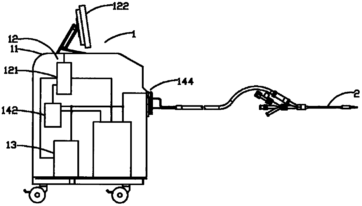
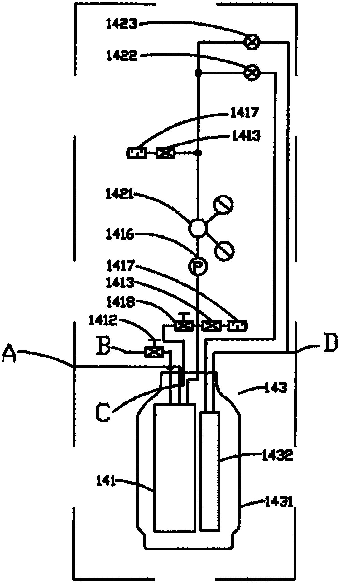
[0028] Such as figure 1 , 2 As shown in and 3, the self-pressurizing cryoablation system of the present invention includes a cryoablation device 1 and a cryoablation catheter 2. The cryoablation device 1 includes a housing 11, a control unit 12, a vacuum unit 13, and a delivery unit 14. The conveying unit 14 includes a gas source manufacturing device 141, a gas path control device 142, a low temperature conversion device 143, and an equipment connector 144 that are sequentially connected. The gas outlet end of the equipment connector 144 and the vacuum unit 13 are connected to the refrigeration unit 13 respectively. The ablation catheter 2 is in fluid communication, the cryogenic conversion device 143 includes a Dewar 1431 and a heat exchanger 1432, the gas source manufacturing device 141 is arranged in the Dewar 1431, and the gas output of the gas source manufacturing device 141 End is in fluid communication with the air inlet port 1421 of the air path cont...

Example Embodiment

[0034] Embodiment two:

[0035] Such as Figure 4 , 5 As shown in 6, this embodiment is based on the first embodiment, and the difference of the first embodiment is only: the structure of the heat exchanger 1432 is different. Such as Figure 4 As shown, the heat exchanger 1432 is a spiral tube structure, which increases the heat exchange area of ​​the gaseous coolant in the Dewar 1431 and the coolant energy exchange, and the spiral tube structure can effectively reduce the coolant in the heat exchanger 1432 Flow resistance within; such as Figure 5 As shown, the heat exchanger 1432 has a horizontal serpentine tube structure, which increases the heat exchange area of ​​the gaseous coolant in the Dewar 1431 and the liquid coolant energy exchange, and can minimize the heat exchanger in the Dewar 1431 Internal space consumption improves the compactness of the system; such as Image 6 As shown, the heat exchanger 1432 has a longitudinal serpentine tube structure, which increases the ...


PUM


Abstract

The invention relates to a self-pressurizing cryoablation system, which comprises cryoablation equipment and a cryoablation catheter, wherein the cryoablation equipment comprises a control unit, a vacuum unit and a delivery unit; the delivery unit comprises an air source manufacturing device, an air path control device, a low-temperature conversion device and an equipment connecting piece which are sequentially connected; the air outlet end and the vacuum unit of the equipment connecting piece are communicated with the cryoablation catheter; the low-temperature conversion device comprises a dewar bottle and a heat exchanger; the air source manufacturing device is arranged in the dewar bottle; the air outlet end of the air source manufacturing device is communicated with the air inlet end of the air path control device; the air source manufacturing device comprises a coolant storage tank, a pressure relief valve communicated with the coolant storage tank, a coolant supplement joint communicated with the coolant storage tank and a heating device arranged in the coolant storage tank; and the control unit is electrically connected with the vacuum unit, the heating device and the air path control device. The large and heavy pressurized air tank without external connector is helpful to save the space of cryoablation equipment.

Description

technical field [0001] The invention relates to the field of cryoablation, in particular to a self-pressurized cryoablation system. Background technique [0002] Cryosurgical treatment is the use of extremely low temperatures and a complex system designed to properly freeze the target biological tissue to be treated. Many of these systems use working fluid from external high-pressure gas tanks connected to the cryoablation catheter through long flexible delivery tubing. These tanks usually have a large internal volume to hold enough working fluid to ensure a typical Cryosurgery procedure. Gas tanks are usually made of steel with very thick walls, which can meet the requirements of high pressure resistance, but at the same time make the gas tanks very bulky. Due to the large size and high pressure required, pressurized gas tanks are generally placed in the freezer The exterior of the ablation unit complicates installation and operation of the system. [0003] The Chinese p...

Claims


Application Information

Patent Timeline
IPC IPC(8): A61B18/02
Inventor 刁月鹏赵奎文姚佳陈陈熙
Owner CRYOFOCUS MEDTECH (SHANGHAI) CO LTD
Why Eureka
Try Eureka