Intraspinal anesthesia support frame for facilitating sitting of patients
A technology of spinal canal and sitting position is applied in the field of anesthesia surgery support frame, which can solve the problems of increased workload of medical staff, affecting intraspinal puncture, prolonging operation time, etc., so as to facilitate intraspinal anesthesia operation and reduce medical staff assistance , the effect of reducing workload
- Summary
- Abstract
- Description
- Claims
- Application Information
AI Technical Summary
Problems solved by technology
Method used
Image

Examples
specific Embodiment approach 1
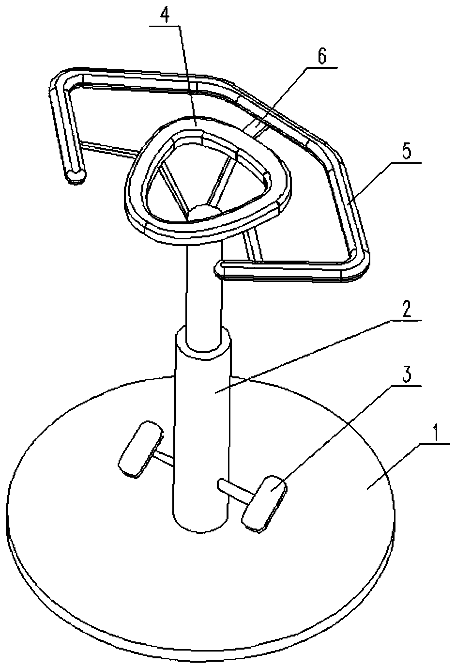
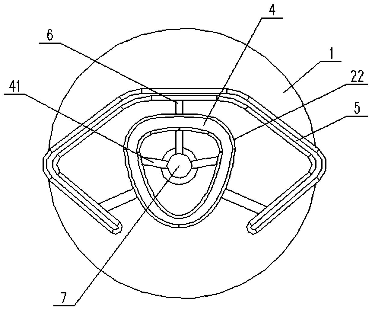
[0029] Specific implementation mode one: combine Figure 1-Figure 10 Describe the present embodiment, the sitting position intraspinal anesthesia stent of the present embodiment includes a base 1, a lifting adjustment mechanism 2, a foot support 3, a head support 4 and a hand support 5, and the center position of the base 1 is vertically installed with a lifting adjustment Mechanism 2, foot support 3 is installed on the lower end of lifting adjustment mechanism 2, and head support 4 is installed on the top of lifting adjustment mechanism 2, and the outer ring of head support 4 is connected with hand support 5 by connecting pipe 6. With this setting, when performing spinal anesthesia, the patient sits on the bed, puts both feet on the foot support 3, supports the hands on the hand support 5, and buries the head slightly lower on the head support 4. At this time, the patient's spine is curved state, adjust the lifting adjustment mechanism 2, so that the patient is in a comfortab...
specific Embodiment approach 2
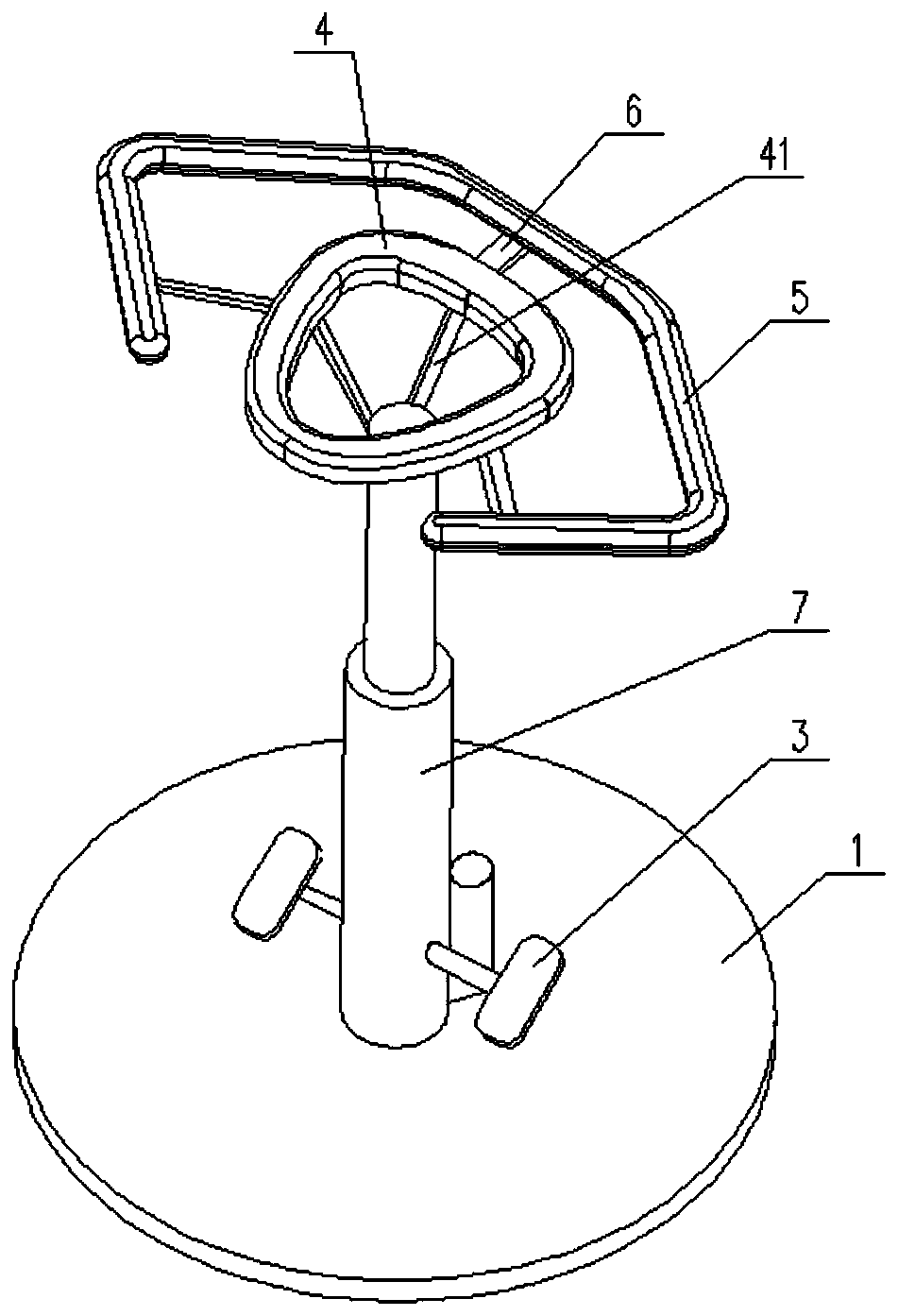
[0030] Specific implementation mode two: combination Figure 1-Figure 10 Describe this embodiment, the sitting position intraspinal anesthesia stent of this embodiment, the described lifting adjustment mechanism 2 comprises electric push rod 7, and electric push rod 7 is vertically installed on the center position of base 1, and foot support 3 is fixedly installed on electric push rod. On the cylinder wall of the rod 7, the head holder 4 is welded on the push rod output end of the electric push rod 7 by the head holder connecting pipe 41. Set up like this, the concrete mode of operation of adjusting lifting adjustment mechanism 2 is, by adjusting the lifting of electric push rod 7, complete the height adjustment of head rest 4 and hand rest 5 relative to base 1, whole device is adjusted flexibly, convenient.
specific Embodiment approach 3
[0031] Specific implementation mode three: combination Figure 1-Figure 10 Describe this embodiment, the sitting position intraspinal anesthesia stent of this embodiment, described elevating adjustment mechanism 2 comprises outer casing 8, inner casing 9 and limit device 10, and outer casing 8 is vertically installed in the center position of base 1, One end of the inner sleeve 9 is slidably inserted in the outer sleeve 8, and the other end of the inner sleeve 9 is welded with the head holder 4 through the head holder connecting pipe 41. The outer wall of the outer sleeve 8 is equipped with a limiting device 10, which limits The positioning device 10 can define the installation position of the inner sleeve 9 inside the outer sleeve 8 . So set, the present embodiment adopts a structural design of a limiting device 10 to limit the relative position of the outer sleeve 8 and the inner sleeve 9, while the prior art often adopts ordinary limiting bayonets to snap into the bayonet h...
PUM
 Abstract
Description
Claims
Application Information
 - R&D
- Intellectual Property
- Life Sciences
- Materials
- Tech Scout
- Unparalleled Data Quality
- Higher Quality Content
- 60% Fewer Hallucinations
Browse by: Latest US Patents, China's latest patents, Technical Efficacy Thesaurus, Application Domain, Technology Topic, Popular Technical Reports.
© 2025 PatSnap. All rights reserved.Legal|Privacy policy|Modern Slavery Act Transparency Statement|Sitemap|About US| Contact US: help@patsnap.com