Mechanical arm device with return and reversal function

A manipulator and functional technology, applied in the field of manipulators, can solve the problems of poor turning stability, poor reliability, traditional structure, etc., and achieve the effect of reliable clamping and improved stability

Inactive Publication Date: 2019-06-21
ZHENGZHOU UNIVERSITY OF AERONAUTICS
View PDF1 Cites 7 Cited by
  • Summary
  • Abstract
  • Description
  • Claims
  • Application Information

AI Technical Summary

Problems solved by technology

The device has poor turning stability, and the clamping and fixing structure for materials is traditional and poor in reliability.

Method used


Image

  • Mechanical arm device with return and reversal function
  • Mechanical arm device with return and reversal function
  • Mechanical arm device with return and reversal function

Examples


Embodiment 1

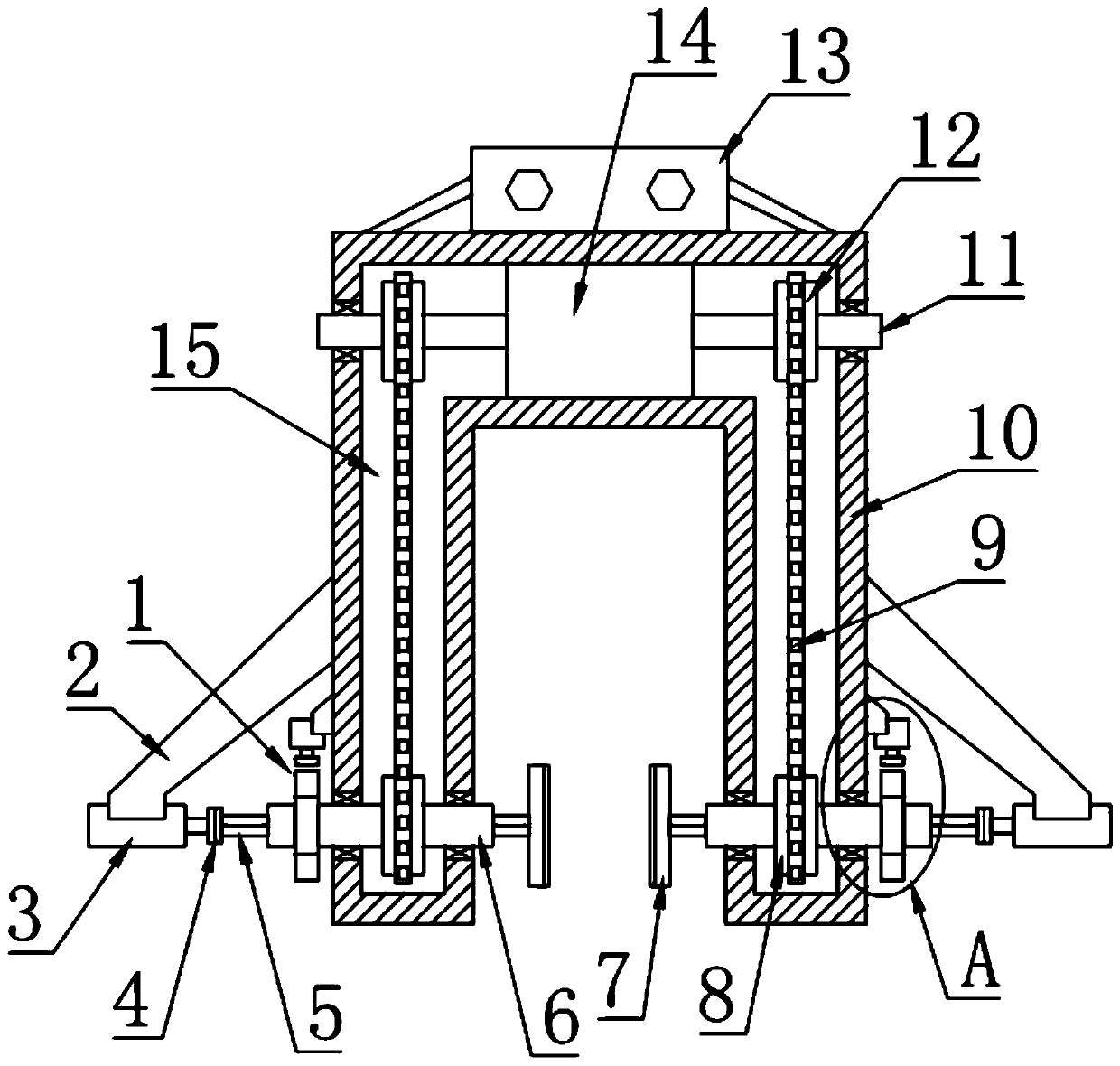
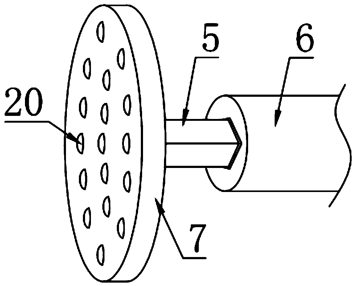
[0025] see Figure 1~4 , in the embodiment of the present invention, a manipulator device with the function of returning and turning includes a U-shaped housing 10, and a U-shaped cavity 15 is opened in the U-shaped housing 10, and a double The shaft extension motor 14 and the lower parts of both sides of the U-shaped cavity 15 are respectively equipped with sleeves 6. The biaxial extension motor 14 is connected with the two sleeves 6 through the transmission mechanism, and the biaxial extension motor 14 is used to drive the two sleeves at the same time. 6 rotates, the sleeve 6 is provided with a clamping rod 5 for sliding cooperation, the inner end of the clamping rod 5 is fixedly provided with a splint 7, and the outer end of the clamping rod 5 is connected with the clamping telescopic cylinder 3 through the rotating body 4, The clamping telescopic cylinder 3 is fixedly arranged on the outside of the U-shaped housing 10 through the first support frame 2 .

[0026] In this e...

Embodiment 2

[0031] see Figure 1~4 , the difference between this embodiment and embodiment 1 is:

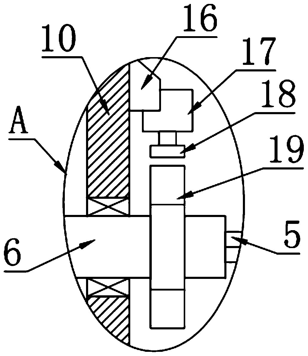
[0032] In this embodiment, the outside of the U-shaped housing 10 is also provided with a return brake assembly 1, and the return brake assembly 1 includes a second support frame 16, a brake telescopic cylinder 17, a brake block 18 and Brake ring plate 19, the brake ring plate 19 is a regular polygon structure, the brake ring plate 19 is provided with a through hole 21 matching with the sleeve 6, the brake ring plate 19 is sleeved and fixed on the sleeve 6 , and the brake ring plate 19 is fixedly connected with the sleeve 6, the brake ring plate 19 is provided with a brake telescopic cylinder 17, and the brake telescopic cylinder 17 passes through the second support frame 16 and the U-shaped shell The outer wall of the body 10 is connected and fixed, and the lower end of the piston rod of the brake telescopic cylinder 17 is equipped with a brake block 18 that can be closely matched with the...


PUM


Abstract

The invention relates to the technical field of mechanical arms, in particular to a mechanical arm device with a return and reversal function. The mechanical arm device with the return and reversal function includes a U-shaped shell body; a U-shaped cavity is formed in the U-shaped shell body, and a double-axis extension motor is installed in the middle of the upper part of the U-shaped cavity; sleeves are correspondingly installed on the lower parts of the two sides of the U-shaped cavity, and the double-axis extension motor is connected with the two sleeves through a transmission mechanism;and clamping rods are slidably arranged in the sleeves in a matched mode, and clamping plates are fixedly arranged at the inner ends of the clamping rods, and the outer ends of the clamping rods are connected with clamping expansion cylinders arranged on the outer side of the U-shaped shell body through a rotating body. According to the mechanical arm device with the return and reversal function,the structure of reversing, braking, clamping and returning is novel, the design is reasonable, and the work efficiency and the reliability are effectively improved.

Description

technical field [0001] The invention relates to the technical field of manipulators, in particular to a manipulator device with a return and flip function. Background technique [0002] A manipulator is an automatic operating device that can imitate certain movement functions of the human hand and arm to grab, carry objects or operate tools according to a fixed program. The feature is that various expected operations can be completed through programming, and the structure and performance have both the advantages of man and robot. The manipulator is the earliest industrial robot and the first modern robot. It can replace the heavy labor of people to realize the mechanization and automation of production, and can operate in harmful environments to protect personal safety. Therefore, it is widely used in machinery manufacturing, metallurgy, Departments of electronics, light industry and atomic energy. [0003] Flip manipulators are widely used in the fields of food packaging ...

Claims


Application Information

Patent Timeline
IPC IPC(8): B25J15/02B25J15/08
Inventor 王昭赵紫浩李梦姝常涛
Owner ZHENGZHOU UNIVERSITY OF AERONAUTICS
Why Eureka
Try Eureka