
Automatic chip feeding device for printed circuit board welding

An automatic feeding and circuit board technology, applied in the field of machining, can solve problems such as large, bulky, complex structure, etc.

Inactive Publication Date: 2019-06-21
夏安祥
View PDF0 Cites 18 Cited by
  • Summary
  • Abstract
  • Description
  • Claims
  • Application Information

AI Technical Summary

Problems solved by technology

However, there are few existing automatic chip feeding devices for circuit board welding, most of which are bulky and bulky, and have complex structures. Therefore, it is necessary to design an automatic chip feeding device for circuit board welding with a simple structure and easy use.

Method used


Image

  • Automatic chip feeding device for printed circuit board welding
  • Automatic chip feeding device for printed circuit board welding
  • Automatic chip feeding device for printed circuit board welding

Examples


Embodiment Construction

[0028] The technical solutions of the present invention will be further described below in conjunction with the accompanying drawings and through specific implementation methods.

[0029] Wherein, the accompanying drawings are only for illustrative purposes, showing only schematic diagrams, rather than physical drawings, and should not be construed as limitations on this patent; in order to better illustrate the embodiments of the present invention, some parts of the accompanying drawings will be omitted, Enlargement or reduction does not represent the size of the actual product; for those skilled in the art, it is understandable that certain known structures and their descriptions in the drawings may be omitted.

[0030] In the drawings of the embodiments of the present invention, the same or similar symbols correspond to the same or similar components; , "inner", "outer" and other indicated orientations or positional relationships are based on the orientations or positional ...


PUM


Abstract

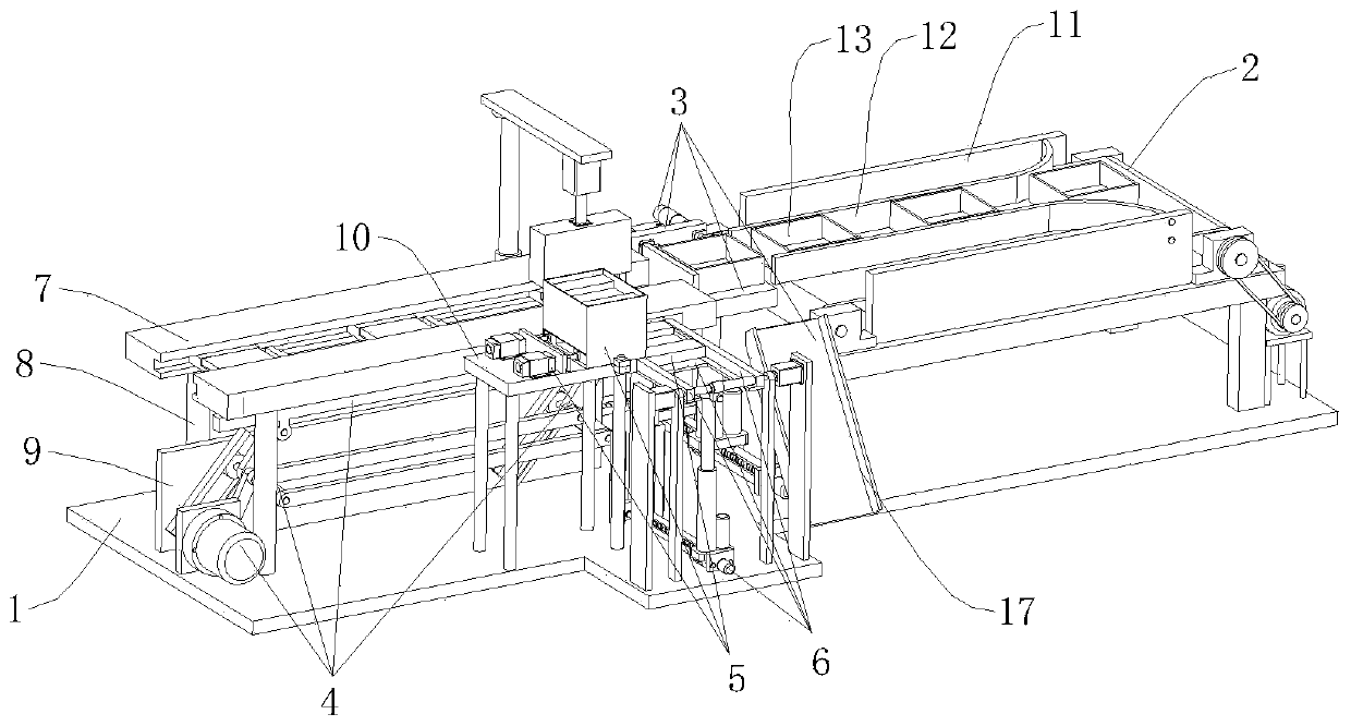
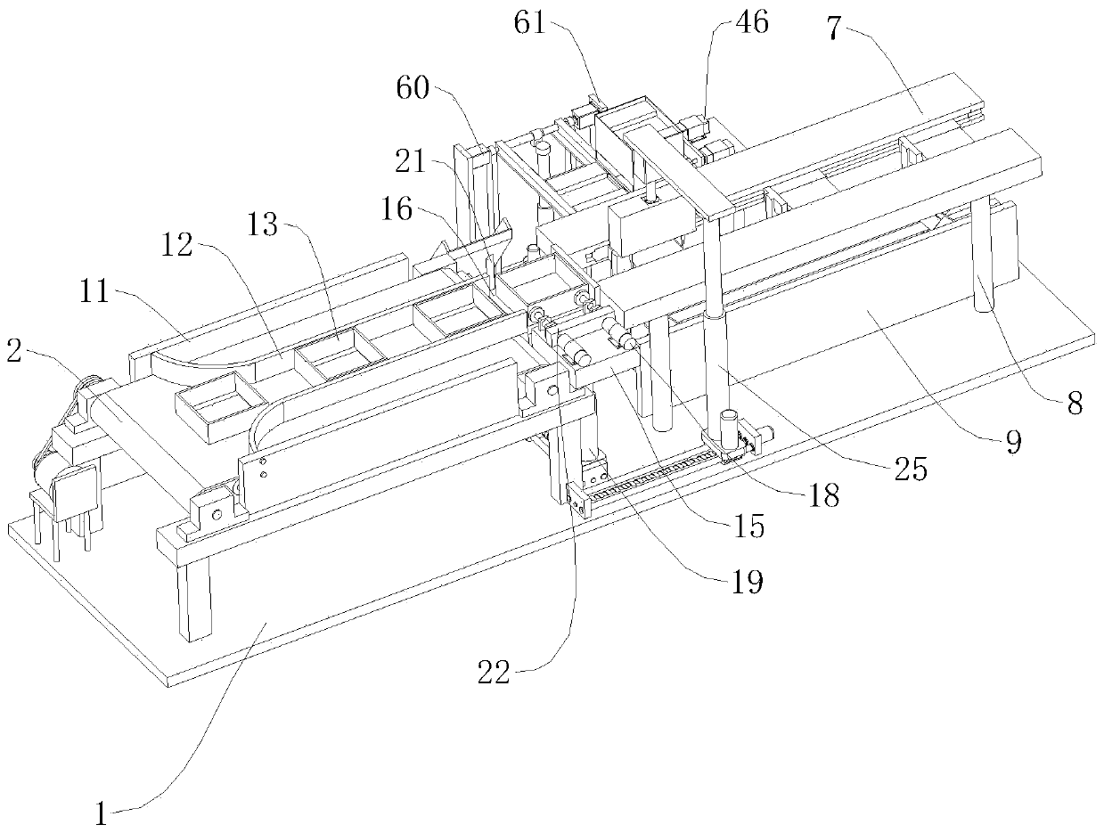
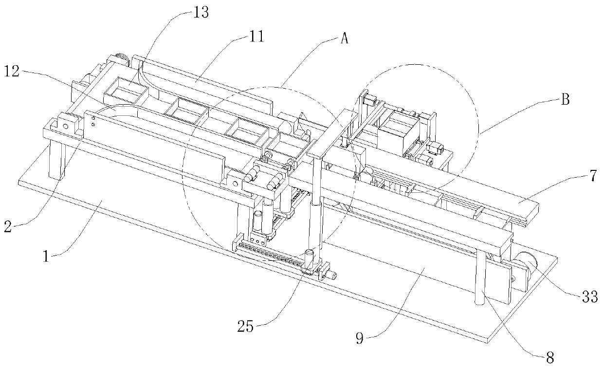
The invention relates to the field of machining, in particular to an automatic chip feeding device for printed circuit board welding. The automatic chip feeding device comprises a base, and further comprises a feeding mechanism, a clamping mechanism and a material moving mechanism, wherein the feeding mechanism comprises a conveyor and a pushing and separating assembly; the material moving mechanism comprises a driving assembly, a feeding assembly, a pushing assembly and two symmetrically-arranged guide rails, wherein the two guide rails are both arranged right above the base through first supporting rods, the driving assembly is vertically arranged between two workbenches through a first fixing plate, the pushing assembly is horizontally arranged at the end, close to the pushing and separating assembly, of one of the workbenches, and is perpendicular to the workbenches; and the feeding assembly is horizontally arranged at the end, close to the workbenches, of the pushing assembly through a first supporting plate and is perpendicular to the workbenches. The automatic chip feeding device for printed circuit board welding has the advantages that the structure is simple, the use is convenient, the automation degree is high, the fatigue degree of workers is reduced, and the production efficiency is improved.

Description

technical field [0001] The invention relates to the field of mechanical processing, in particular to an automatic chip feeding device for circuit board welding. Background technique [0002] Circuit boards, circuit boards, PCB boards and other soldering technologies have developed in the electronics industry in recent years. It can be noticed that an obvious trend is reflow soldering technology. In principle, traditional plug-in parts can also be used in reflow soldering process, which is commonly referred to as through-hole reflow soldering. The advantage is that it is possible to complete all solder joints at the same time, keeping production costs to a minimum. However, temperature-sensitive components limit the application of reflow soldering, whether it is a plug-in or SMD. Then people turn their attention to selective soldering. Selective soldering can be used after reflow soldering in most applications. This will become an economical and effective method of solderi...

Claims


Application Information

Patent Timeline
Patent Type & Authority Applications(China)
IPC IPC(8): B65G47/90B65G47/82B65G47/24B65G11/02B23K3/08
Inventor 夏安祥
Owner 夏安祥
Learn More