
Environmental device for cleaning viscous garbages

A technology for environmental protection equipment and garbage, which is applied in road cleaning, cleaning methods, construction, etc., can solve problems such as increasing the workload of sanitation workers, black spot stains, and ground pollution, so as to improve the efficiency of sanitation work, save cleaning procedures, and improve The effect of work efficiency

Inactive Publication Date: 2019-06-21
苏州知遇光电科技有限公司
View PDF0 Cites 1 Cited by
  • Summary
  • Abstract
  • Description
  • Claims
  • Application Information

AI Technical Summary

Problems solved by technology

[0002] At present, there are all kinds of sticky food on the market. The discarded sticky food adheres to the ground and causes serious pollution to the ground of public places, and it is very difficult to clean up, which brings a heavy workload to sanitation workers. ;In some public places with a large flow of people, the amount of chewing gum and other sticky garbage after eating is extremely large. Due to the heavy workload, sanitation workers can only give up cleaning it; it is easy to form a lump on the ground for a long time A piece of black spots and stains will affect public sanitation and at the same time affect the image of the city
When cleaning the sticky garbage attached to the ground, first remove the sticky garbage, then collect it, and finally clean the stains left by the sticky garbage on the ground; cleaning of sticky garbage The division is cumbersome, which increases the workload of sanitation workers, and the work efficiency is not high; in view of the shortcomings of the above-mentioned traditional cleaning of sticky garbage on the ground, we need to design a collection of eradication, collection and stain cleaning. equipment to clean up sticky waste on the ground in public places

Method used


Image

  • Environmental device for cleaning viscous garbages
  • Environmental device for cleaning viscous garbages
  • Environmental device for cleaning viscous garbages

Examples


Embodiment Construction

[0035] The drawings are schematic diagrams of the implementation of the present invention to facilitate the understanding of the operating principle of the structure. The specific product structure and proportional size can be determined according to the use environment and conventional technology.

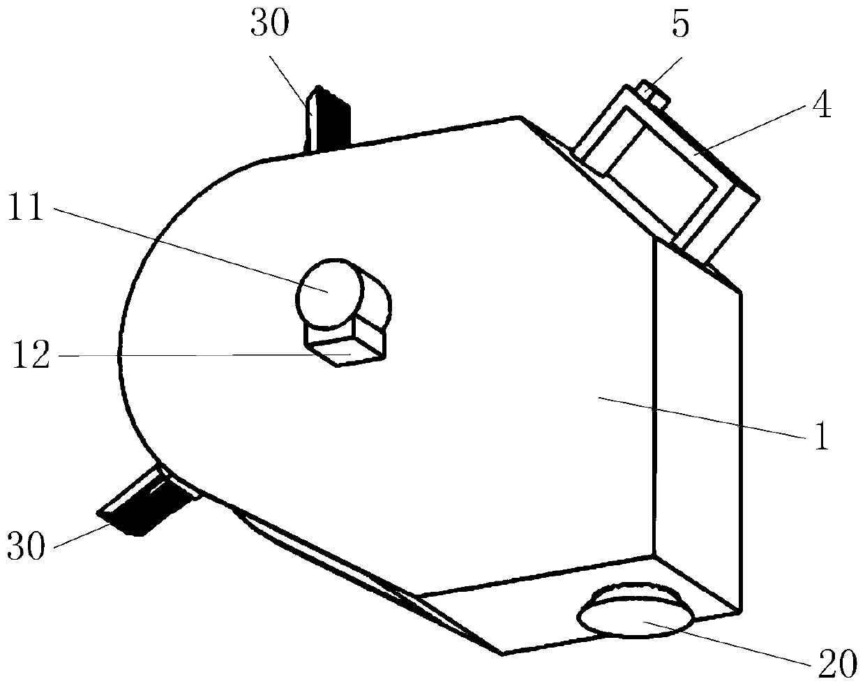
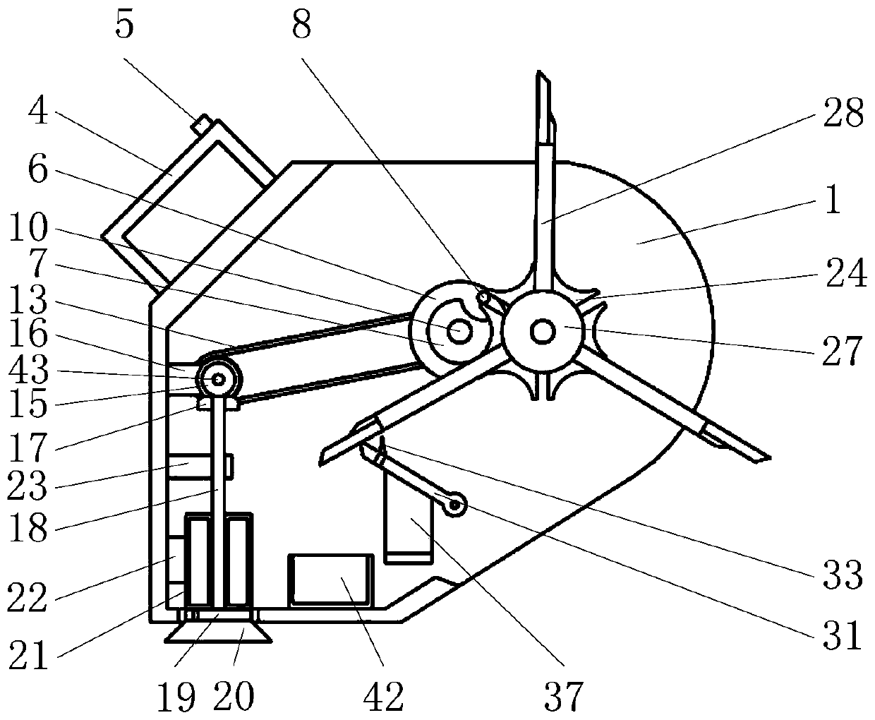
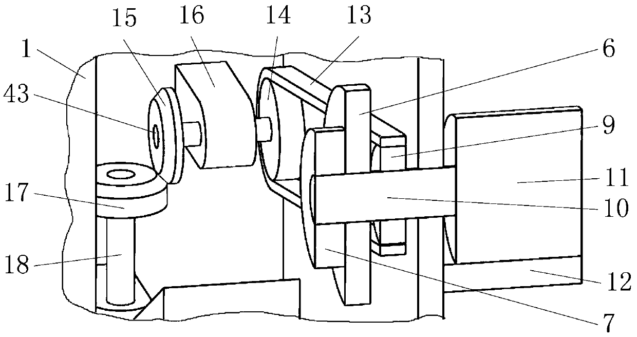
[0036] Such as figure 1 , 2 As shown, it includes a housing 1, a handle 4, a switch button 5, a dial 6, a locking disk 7, a dial pin 8, a transmission shaft A10, an electric drive module 11, a transmission shaft C18, a brush holder 19, a cone brush 20, and a ring Bucket 21, sheave wheel 24, shaft sleeve 27, strip swing plate 28, shovel block 29, shovel plate 30, U-shaped swing plate 31, wedge scraper 33, scroll spring 34, soft bladder 37, collection box 42, wherein Such as image 3 , 5 As shown in 6, the interconnected dial 6 and the locking disk 7 are concentrically mounted on the inner wall of the housing 1 through the drive shaft A10, and the drive shaft A10 is matched with the sh...


PUM


Abstract

The invention belongs to the field of environmental protection and cleaning, especially relates to an environmental protection device for cleaning viscous garbages. The device comprises a housing, a electric drive module, a strip swing plate and a collection box, wherein a dial plate and locking plate interconnecting with each other are concentrically installed on the inner wall of the housing through a transmission shaft A, and the transmission shaft A is bearing fit with the shaft hole on the side wall of the housing; a shovel plate in the invention carries out the preliminary elimination ofthe viscous garbage on the ground, and a shovel block further eliminates the viscous garbages or stubborn viscous garbages which are not eliminated by the shovel plate on the ground; the viscous garbages that are scooped up from the ground stick to the shovel plate or the shovel block, and through the interaction between the teeth and wedge scraping blades on a U-shaped swing plate and the shovelplate or the shovel block, the viscous garbages that stick to the shovel plate or the shovel block are cut off and fall into the collection box below.

Description

Technical field [0001] The invention belongs to the field of environmental protection and cleaning, and in particular relates to an environmental protection device for cleaning sticky garbage. Background technique [0002] At present, there are all kinds of viscous food on the market. The discarded viscous food adheres to the ground, causing serious pollution to the ground of public places, and it is very difficult to clean up, which brings a heavy workload to sanitation workers. ; In some public places with a large flow of people, there are a lot of sticky garbage such as chewing gum after eating. Due to the heavy workload, sanitation workers can only give up cleaning it; sticking to the ground for a long time will easily form a piece A piece of black spot stains affects public sanitation and the image of the city. When cleaning up the sticky garbage adhering to the ground, first remove the sticky garbage, then collect it, and finally clean the stains left by the sticky garbage...

Claims


Application Information

Patent Timeline
IPC IPC(8): E01H1/00E01H1/05
Inventor 钱理
Owner 苏州知遇光电科技有限公司
Learn More