A method for calibrating multi-camera visual inspection equipment

A technology of multi-camera vision and detection equipment, applied in image analysis, instrumentation, computing, etc., can solve problems such as complex operation and low efficiency

Active Publication Date: 2020-06-26
易思维(杭州)科技股份有限公司
View PDF3 Cites 2 Cited by
  • Summary
  • Abstract
  • Description
  • Claims
  • Application Information

AI Technical Summary

Problems solved by technology

The traditional multi-camera calibration method is inefficient, complicated to operate and requires professionals to complete the calibration

Method used


Image

  • A method for calibrating multi-camera visual inspection equipment
  • A method for calibrating multi-camera visual inspection equipment
  • A method for calibrating multi-camera visual inspection equipment

Examples


Embodiment 1

[0047] In this embodiment, the case where the number of cameras is 3 is listed, a method for calibrating multi-camera visual inspection equipment, the multi-camera visual inspection equipment is set in industrial equipment (specifically, this industrial equipment can be a glue gun, or can be It is other similar equipment), and 3 cameras are evenly distributed on the circumference with the center of the detection equipment as the center, and the angle between two adjacent cameras is 120°, including the following steps:

[0048] Step 1. Place the calibration plate under the detection equipment. The calibration plate includes 3 characteristic mark circles with unequal diameters; the centers of the 3 feature mark circles are located on the same circumference of the calibration plate; The angle is also 120°, corresponding to the camera position one by one;

[0049]Adjust the position of the multi-camera visual inspection equipment so that the field of view of a single camera contai...

Embodiment 2

[0066] A method for calibrating multi-camera visual inspection equipment. The multi-camera visual inspection equipment is set on industrial equipment (specifically, the industrial equipment can be a glue gun or other similar equipment), and the inspection equipment center 3 cameras are evenly distributed on the circumference of the circle center, and the angle between two adjacent cameras is 120°, such as figure 2 shown, including the following steps:

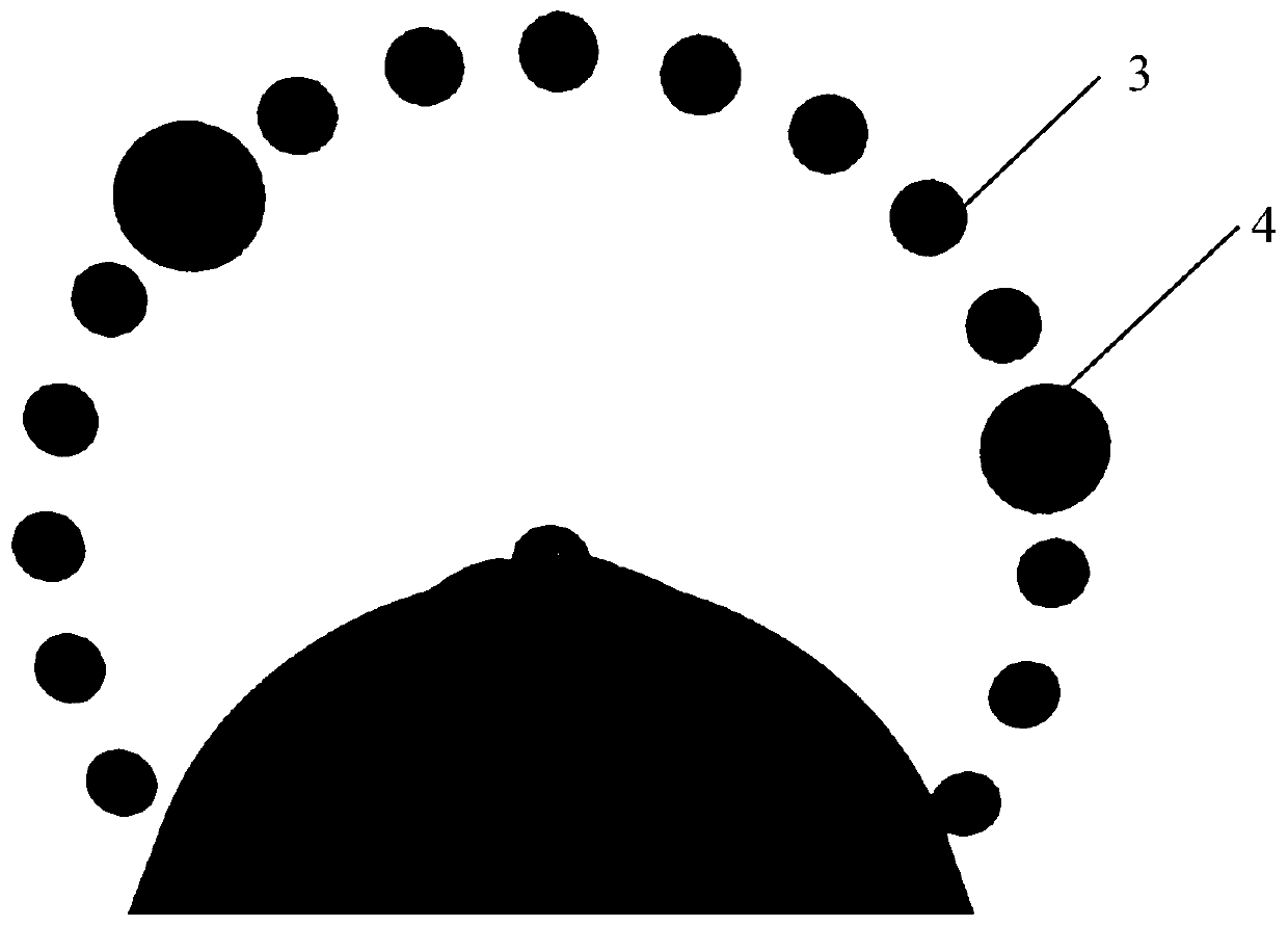
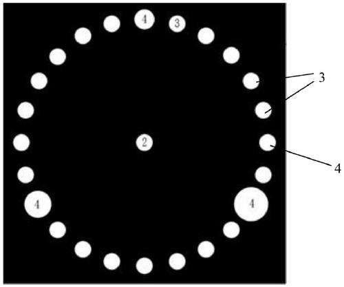
[0067] Step 1. Place the calibration plate under the testing equipment, such as image 3 As shown, the calibration plate includes a plurality of equal common sign circles 3 with equal diameters and three characteristic sign circles 4 with unequal diameters; the centers of the common sign circles 3 and the feature sign circles 4 are located on the same circumference, and the circle is denoted as circle I; The diameter of characteristic sign circle 4 is greater than the diameter of common sign circle 3; The center position of c...


PUM


Abstract

The invention discloses a method for calibrating multi-camera visual inspection equipment. The multi-camera visual inspection equipment is sleeved on industrial equipment, and N cameras are uniformlydistributed on the circumference taking the center of the detection equipment as the center of a circle, and the method comprises the following steps: 1, placing a calibration plate below the detection equipment with the calibration plate comprising a plurality of common mark circles with equal diameters and N characteristic mark circles with unequal diameters; locating The center of the common mark circle and the center of the characteristic mark circle on the same circumference. wherein the diameter of the characteristic mark circle is different from that of a common mark circle; Wherein theview field of each camera at least comprises one characteristic mark circle; enabling the N camera fields of view to cover the whole calibration plate after being spliced; utilizing an image processing method to fit circle centers and radiuses of the common mark circle and the characteristic mark circle, and determining a camera number according to the size of the characteristic mark circle; andfitting the circle center and the radius of the large circle by using the fitted circumferential contour line, and calibrating the coordinate position and the pixel equivalent of the center of the detection equipment.

Description

technical field [0001] The invention relates to the field of camera calibration, in particular to a method for calibrating multi-camera visual inspection equipment. Background technique [0002] In the modern automated production process, people widely use machine vision systems in various industries. Machine vision systems can greatly improve production efficiency and automation of production, and machine vision has higher accuracy than artificial vision. With the popularization of machine vision in industry, high-precision industrial production equipment has put forward high-precision and large-field requirements for machine vision. It is difficult for a single camera to achieve high precision and large field of view at the same time. Accuracy and large field of view requirements. [0003] However, multi-camera needs to use a high-precision calibration plate to calibrate the coordinate transformation relationship between the cameras to achieve the requirements of high pr...

Claims


Application Information

Patent Timeline
Patent Type & Authority Patents(China)
IPC IPC(8): G06T7/80
Inventor 周鹏冯宇深曹军旗叶琨
Owner 易思维(杭州)科技股份有限公司
Why Eureka
Try Eureka