Branch identification and switch state monitoring device and method based on wideband carrier

A technology of switch state and broadband carrier, applied in the direction of fault location, signal transmission system, instrument, etc., can solve the problems of not being able to know the switch state and measurement data such as voltage, current, power, and electricity, monitoring blind spots, and low automation level. Achieve the effect of meeting high-speed collection requirements, reducing construction difficulty, and simple structure

Inactive Publication Date: 2019-06-21
国网福建省电力有限公司漳浦县供电公司 +2
View PDF6 Cites 11 Cited by
  • Summary
  • Abstract
  • Description
  • Claims
  • Application Information

AI Technical Summary

Problems solved by technology

[0002] The power supply network of the low-voltage station area is the end of the power grid. Due to the large number of equipment and low automation level, there are many blind spots in management; especially the power supply equipment between the station area and the low-voltage user has been in the equipment monitoring blind spot.
Due to the lack of effective online monitoring means, users are always aware of power outages, resulting in passive and disordered repair work
In the event of a power outage, due to the lack of the topological relationship of the power supply network in the station area and the current operating status of the power supply network in the station area, it is impossible to quickly and accurately locate the fault point and calculate the scope of the power outage, resulting in repeated and invalid attendance, affecting the efficiency of emergency repairs, and it is difficult to fundamentally improve User Satisfaction with Electricity
[0003] At present, the station area branch identification instrument on the market is an offline handheld device, which cannot be connected to the network to run online. It requires staff to arrive at the scene to control the device to complete the topology identification of the station area power supply network.
Due to the inability to monitor online in real time, when the power supply network in the station area changes, it is impossible to know
[0004] At present, most of the branch switches at all levels of the power supply network in the station area are non-intelligent switches, and there is no effective monitoring means, and it is impossible to know the switch status and measurement data such as voltage, current, power, and electricity.

Method used


Image

  • Branch identification and switch state monitoring device and method based on wideband carrier
  • Branch identification and switch state monitoring device and method based on wideband carrier
  • Branch identification and switch state monitoring device and method based on wideband carrier

Examples


Embodiment 1

[0030] Embodiment one, consult figure 1 with figure 2 :

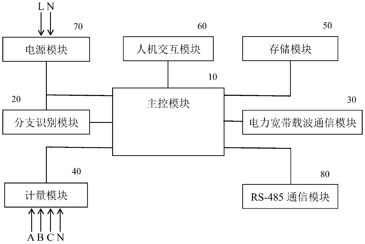
[0031] A branch identification and switch state monitoring device based on a broadband carrier, which includes a main control module 10 with a microcontroller, a branch identification module 20 connected to the main control module, a power broadband carrier communication module 30, a metering module 40, A storage module 50, a human-computer interaction module 60 and a power module 70, the power module 70 provides electric energy for each module;

[0032] The branch identification module 20 is used to couple the characteristic current signal to the power line, analyze the received characteristic current signal on the power line, and pass the result to the main control module for processing; The identification module 20 couples the characteristic current signal to the power line. After receiving the characteristic current signal on the power line, the superior branch identification module 20 in the station area analyze...

Embodiment 2

[0040] A branch recognition method, it comprises the steps:

[0041] Step 1, installing the branch identification and switch state monitoring device based on broadband carrier described in Embodiment 1 at the branch switches at all levels;

[0042] Step 2, sending a characteristic current signal opposite to the direction of the power supply current in the station area through the device described in step 1;

[0043] Step 3, the device installed at each branch switch performs high-speed current sampling, and analyzes the sampled current signal;

[0044] Step 4, if the device at this level analyzes and obtains the characteristic current signal, it is determined that the device at this level is located at the upper level of the device that sends the characteristic current signal;

[0045] By analogy, the topological connection relationship of devices at each branch switch in the station area, that is, the branch relationship, can be identified.

[0046] In this embodiment, the ...

Embodiment 3

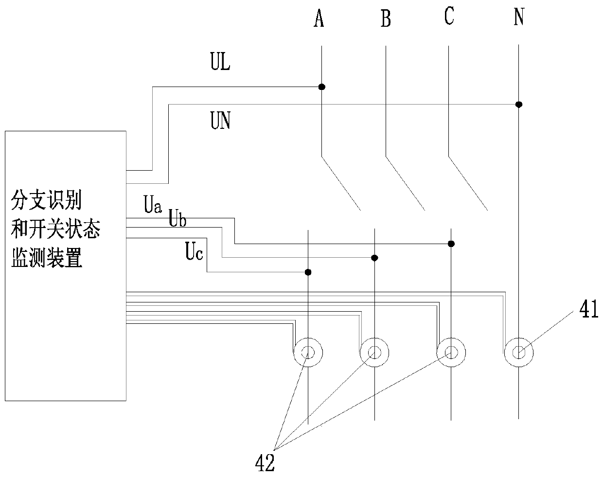
[0048] A switch state monitoring method, which collects the voltage of the incoming line and outgoing line of the branch switch through the branch identification and switching state monitoring device based on the broadband carrier described in the first embodiment, when the voltage difference between the incoming line and the outgoing line is greater than the critical value , it is considered that the branch switch is in the open state, otherwise it is in the closed state.

[0049] The present invention installs branch identification and switch monitoring devices at all levels of branch switch nodes of the station area power supply network to realize automatic identification of the topological connection relationship of the station area power supply network and online monitoring of the operating status of the branch switches to meet the needs of the station area power supply network. Monitor demand in real time.


PUM


Abstract

The invention discloses a branch identification and switch state monitoring device and method based on a wideband carrier. The device comprises a main control module with a micro controller, a branchidentification module, a power broadband carrier communication module, a metering module, a storage module, a human-machine interaction module and a power module. The branch identification module is configured to couple a characteristic current signal to a power line and parse the characteristic current signal received on the power line. The metering module is configured to acquire three-phase voltage and current signals inputted into the model and transmit current and voltage data to the main control module. The power broadband carrier communication module is used for communication connectionwith the remote terminal to realize data interaction between the remote terminal and the main control module. After installation of branch identification and switch state monitoring devices at all branch switch nodes of the court power supply network, automatic identification of the topology connection relationship of the court power supply network as well as on-line monitoring of the branch switch operation statuses is realized, thereby meeting the real-time monitoring requirement of the court power supply network.

Description

technical field [0001] The invention relates to a branch identification and switch state monitoring device and a branch identification and switch state monitoring method based on a broadband carrier. Background technique [0002] The power supply network of the low-voltage station area is the end of the power grid. Due to the large number of equipment and low automation level, there are many blind spots in management; especially the power supply equipment between the station area and the low-voltage users has always been in the blind spot of equipment monitoring. Due to the lack of effective online monitoring means, users are always aware of power outages, resulting in passive and disordered repair work. In the event of a power outage, due to the lack of the topological relationship of the power supply network in the station area and the current operating status of the power supply network in the station area, it is impossible to quickly and accurately locate the fault point...

Claims


Application Information

Patent Timeline
Patent Type & Authority Applications(China)
IPC IPC(8): G08C19/00G01R31/08
Inventor 江毅郑颖雅洪民军
Owner 国网福建省电力有限公司漳浦县供电公司
Why Eureka
Try Eureka