Supercharge Your Innovation With Domain-Expert AI Agents!

Image stabilization method and system based on improved line scanning imaging system

An imaging system and line-scanning technology, applied in the fields of eye testing equipment, medical science, ophthalmoscope, etc., can solve problems such as optical and control defects, and achieve the effect of improving spatial precision and time bandwidth

Pending Publication Date: 2019-06-25
BRIGHTVIEW MEDICAL TECH NANJING CO LTD
View PDF1 Cites 11 Cited by
  • Summary
  • Abstract
  • Description
  • Claims
  • Application Information

AI Technical Summary

Problems solved by technology

[0003] In view of this, the main purpose of the present invention is to provide an image stabilization method and system based on an improved line scan imaging system, which aims to overcome the inherent optical and control defects of the existing LSO imaging system, and greatly improve its clinical application. Stability, accuracy, imaging efficiency in

Method used


Image

  • Image stabilization method and system based on improved line scanning imaging system
  • Image stabilization method and system based on improved line scanning imaging system
  • Image stabilization method and system based on improved line scanning imaging system

Examples


Embodiment Construction

[0040] The present invention will be further described in detail below in conjunction with the accompanying drawings and the embodiments of the present invention.

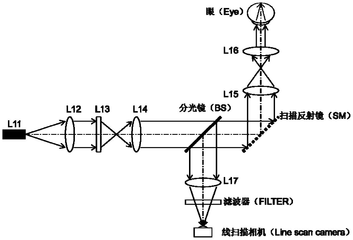
[0041] figure 1 It is a schematic diagram of the optical structure of the existing line scan fundus camera.

[0042] Such as figure 1As shown, the light emitted from the point light source L11 is collimated by the lens L12, the surface light source is converted into a line light source by the cylinder lens (CylinderLens) L13, and then relayed to the collimating lens L14. Here, the installation direction of the cylindrical lens L13 determines the expansion direction of the line light source in space (see Figure 9 and Figure 10 ), lens L12, lens L13, and lens L14 determine to a certain extent the illumination (expansion) size of the line light source in the fundus. Part of the light emitted by the lens L14 passes through the beam splitter (BS) and reaches the scanning mirror (Steering Mirror or Scanning Mirror,...


PUM


Abstract

The invention discloses an image stabilization method and system based on an improved line scanning imaging system. The image stabilization system comprises a line scanning fundus camera (LSO) imagingsystem, and the LSO imaging system further comprises an orthogonal galvanometer scanning device for generating the orthogonal scanning surface at the fundus and adjusting the scanning surface to anyposition in a 360-degree space. The orthogonal galvanometer scanning device can be combined with the intelligent control algorithm to perform the fundus optical tracking inside the LSO while performing the two-dimensional fundus scanning. The closed-loop fundus optical tracking system can be established, and the closed-loop tracking system is utilized to control the line scanning imaging system, so that the purpose of high speed, stability and precise control can be achieved.

Description

technical field [0001] The invention relates to laser fundus target tracking and imaging technology, in particular to an image stabilization method and system based on an improved line scanning imaging system. Background technique [0002] Existing target tracking technology based on the Line Scan Ophthalmoscope (LSO) imaging system, such as the imaging system of Carl Zeiss (Carl Zeiss), uses one frame of image as a unit to calculate the amount of movement of the fundus target, But there is a time delay of at least one frame in the control system, which will lead to the defect of reducing the tracking accuracy. Moreover, the target tracking signal method of the existing LSO is completely digital. When the signal is extracted from the image, the calculation of the fundus motion signal is not very reliable due to the lack of optical closed-loop control measures inside the LSO. Contents of the invention [0003] In view of this, the main purpose of the present invention is t...

Claims


Application Information

Patent Timeline
IPC IPC(8): A61B3/12A61B3/14
CPCA61B3/12A61B3/14
Inventor 张杰张金莲
Owner BRIGHTVIEW MEDICAL TECH NANJING CO LTD
Features
  • R&D
  • Intellectual Property
  • Life Sciences
  • Materials
  • Tech Scout
  • Unparalleled Data Quality
  • Higher Quality Content
  • 60% Fewer Hallucinations
Learn More