Automatic production line and production manner of centrifugal cast pipes

A technology of automatic production line and centrifugal casting pipe, which is applied in foundry workshops, casting equipment, equipment for supplying molten metal, etc., and can solve problems such as waste of working hours, low production efficiency, and poor control of product quality.

Pending Publication Date: 2019-06-25
SHANGHAI SUPEZET ENG TECH CO LTD +1
View PDF0 Cites 0 Cited by
  • Summary
  • Abstract
  • Description
  • Claims
  • Application Information

AI Technical Summary

Problems solved by technology

[0002] Casting is widely used in the production of large-scale workpieces. With the development of science and technology, people's requirements for craftsmanship are getting higher and higher. The traditional existing casting technology has low production efficiency; there are many manual interventions in the casting process, which is easy Improper operation will cause personal injury and waste of manpower; the production process of castings cannot be tracked, resulting in real-time monitoring. When accidents or product quality problems occur, problems cannot be found, resolved and further improved in time, which will waste a lot of man-hours. The production efficiency is reduced; and the quality of the product cannot be well controlled, so that the quality of the product is uneven and the pass rate is reduced

Method used


Image

  • Automatic production line and production manner of centrifugal cast pipes
  • Automatic production line and production manner of centrifugal cast pipes
  • Automatic production line and production manner of centrifugal cast pipes

Examples


Embodiment Construction

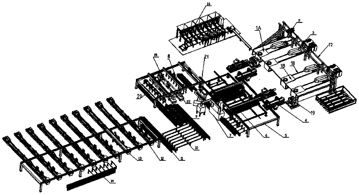
[0027] The present invention will be specifically introduced below in conjunction with the accompanying drawings and specific embodiments.

[0028] An automatic production line and production method for centrifugal casting pipes, including a batching warehouse 16, one end of the batching warehouse 16 is provided with a feeding device, and the feeding device includes a feeding robot 2, four feeding trolleys 3, and a first supporting robot 2 A track 17 and the second track 18 supporting the charging trolley 3, the other end of the second track 18 is provided with a smelting device, the smelting device includes a group of 1T melting furnaces 11 and a group of 2T melting furnaces, and a group of 1T melting furnaces includes two One 1T melting furnace 1A, one group of 2T melting furnaces including two 2T melting furnaces 1B, one group of 1T melting furnaces and one group of 2T melting furnaces including tundish trolley 19 and two centrifuges 4, two groups of melting furnaces with di...


PUM


Abstract

The invention discloses an automatic production line and a production manner of centrifugal cast pipes. The automatic production line comprises a batching library. A feeding device is arranged at oneend of the batching library. The feeding device comprises a feeding robot, four feeding trolleys, first rails for supporting the feeding robot, and second rails for supporting the feeding trolleys. Asmelting device is arranged at the other ends of the second rails, a pipe pulling robot is arranged at the other end of the smelting device, and a steering robot is arranged at the other end of the pipe pulling robot. The steering robot comprises a rotary robot and a sliding rail, a shot blasting machine and a straightening machine are arranged on the other side of the sliding rail, and a head cutting device is arranged at the other end of the straightening machine. The head cutting device comprises a transfer cutting head, a double-head lathe, a laser marking machine and a transfer robot. A PT pond is mounted on one side of the laser marking machine, a transfer passageway is formed in the other side of the PT pond, a first transfer frame is arranged at the other end of the transfer passageway, a boring mill robot is arranged on the other side of the first transfer frame, a boring mill is arranged below the boring mill robot, and a second transfer frame is arranged at the other end ofthe boring mill.

Description

technical field [0001] The invention relates to the field of casting, in particular to an automatic production line and a production method of centrifugal casting pipes. Background technique [0002] Casting is widely used in the production of large-scale workpieces. With the development of science and technology, people's requirements for craftsmanship are getting higher and higher. The traditional existing casting technology has low production efficiency; there are many manual interventions in the casting process, which is easy Improper operation will cause personal injury and waste of manpower; the production process of castings cannot be tracked, resulting in real-time monitoring. When accidents or product quality problems occur, problems cannot be found, resolved and further improved in time, which will waste a lot of man-hours. The production efficiency is reduced; and the quality of the product cannot be well controlled, so that the quality of the product is uneven an...

Claims


Application Information

Patent Timeline
IPC IPC(8): B22D47/00B22D13/02B22D13/10B22D13/12B22D39/04
Inventor 杨经伟张国兵张梦茹陆垚黄凯
Owner SHANGHAI SUPEZET ENG TECH CO LTD
Why Eureka
Try Eureka