
Ice crystal detector and detection method

A detector and ice crystal technology, used in deicing devices, transportation and packaging, optical device exploration, etc., can solve the problems of large electric power consumption and complex structure, and achieve the advantages of increasing surface area, simple structure, and expanding installation and use range. Effect

Active Publication Date: 2019-06-25
COMAC +1
View PDF7 Cites 6 Cited by
  • Summary
  • Abstract
  • Description
  • Claims
  • Application Information

AI Technical Summary

Problems solved by technology

The disadvantage is that the structure of the two conical tubes is complex in structure and consumes a lot of electric power

Method used


Image

  • Ice crystal detector and detection method
  • Ice crystal detector and detection method
  • Ice crystal detector and detection method

Examples


Embodiment Construction

[0071] The present invention will be further described below in conjunction with the accompanying drawings and embodiments, so as to more clearly connect the inventive principle and beneficial technical effects of the present invention.

[0072] Explanation of terms used in this article:

[0073] Windward side: the side facing the airflow;

[0074] Leeward side: the side opposite to the windward side, facing away from the airflow;

[0075] Longitudinal: refers to the installation surface substantially perpendicular to the body on which the detector according to the invention is installed;

[0076] Transverse: refers to the mounting surface on which the detector according to the invention is installed substantially parallel to the body;

[0077] Bottom end: the end of the rod body arranged longitudinally close to the supporting part of the detector;

[0078] Top: the end of the rod body arranged longitudinally away from the supporting part of the detector;

[0079] Bottom: ...


PUM


Abstract

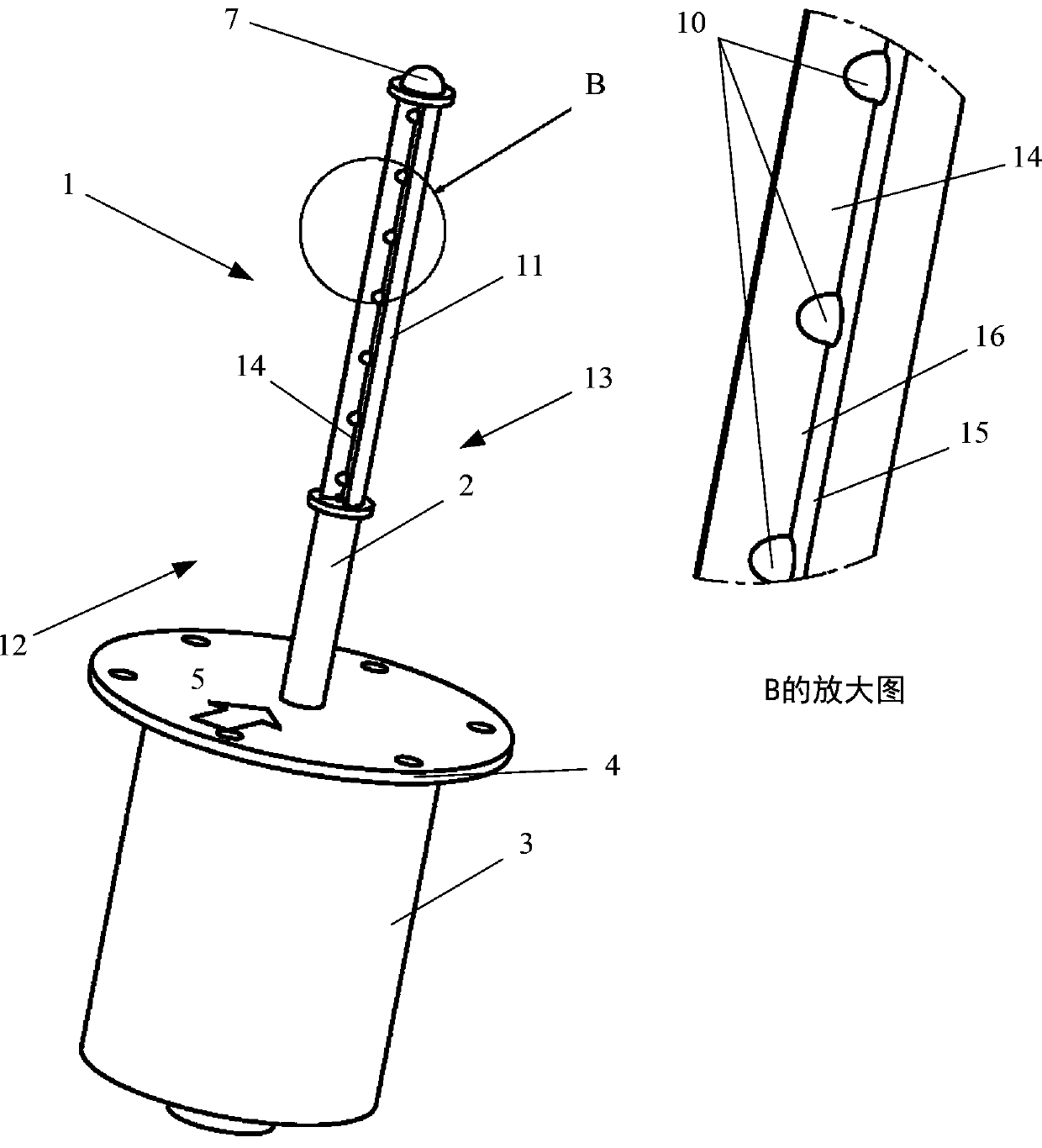
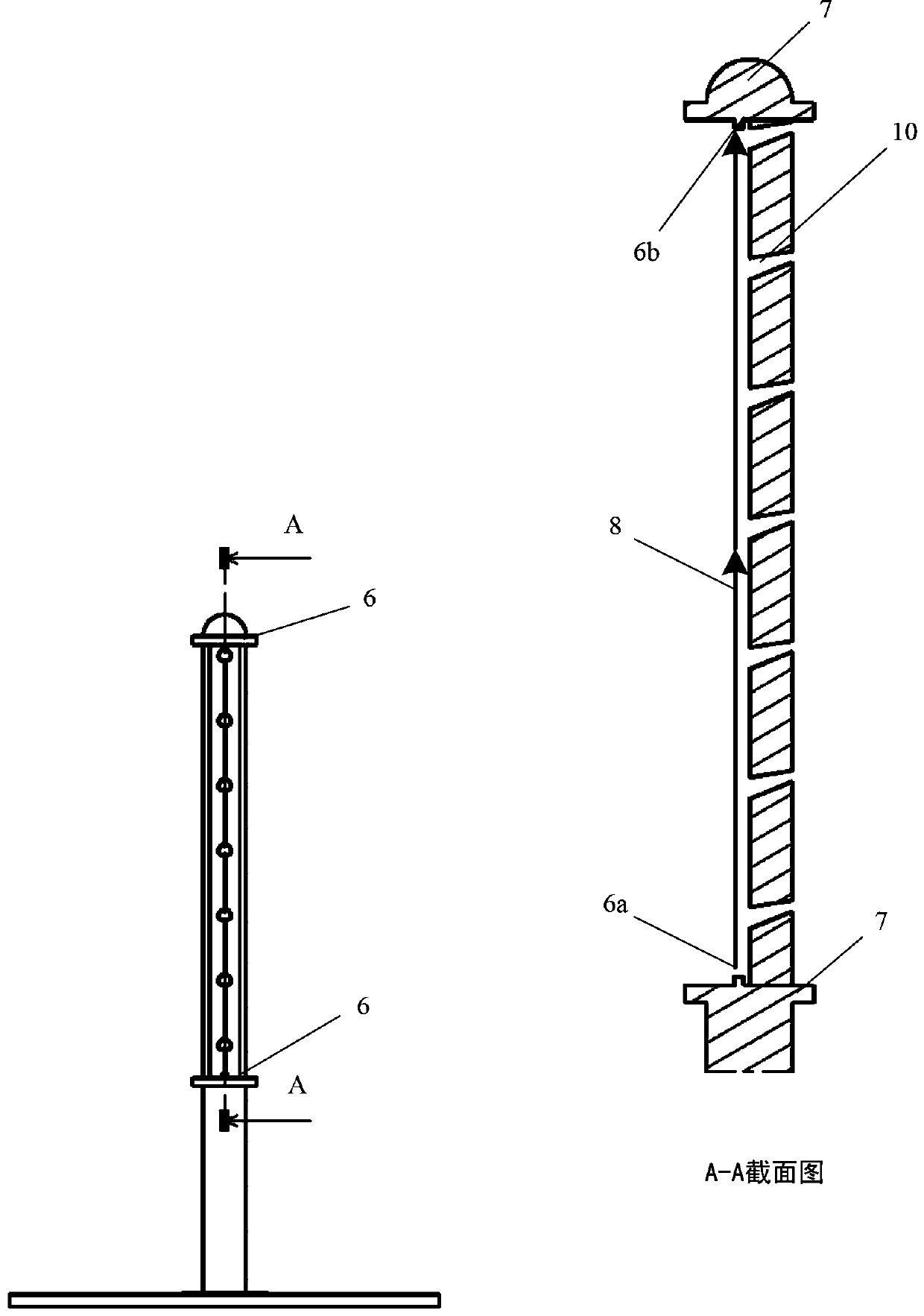
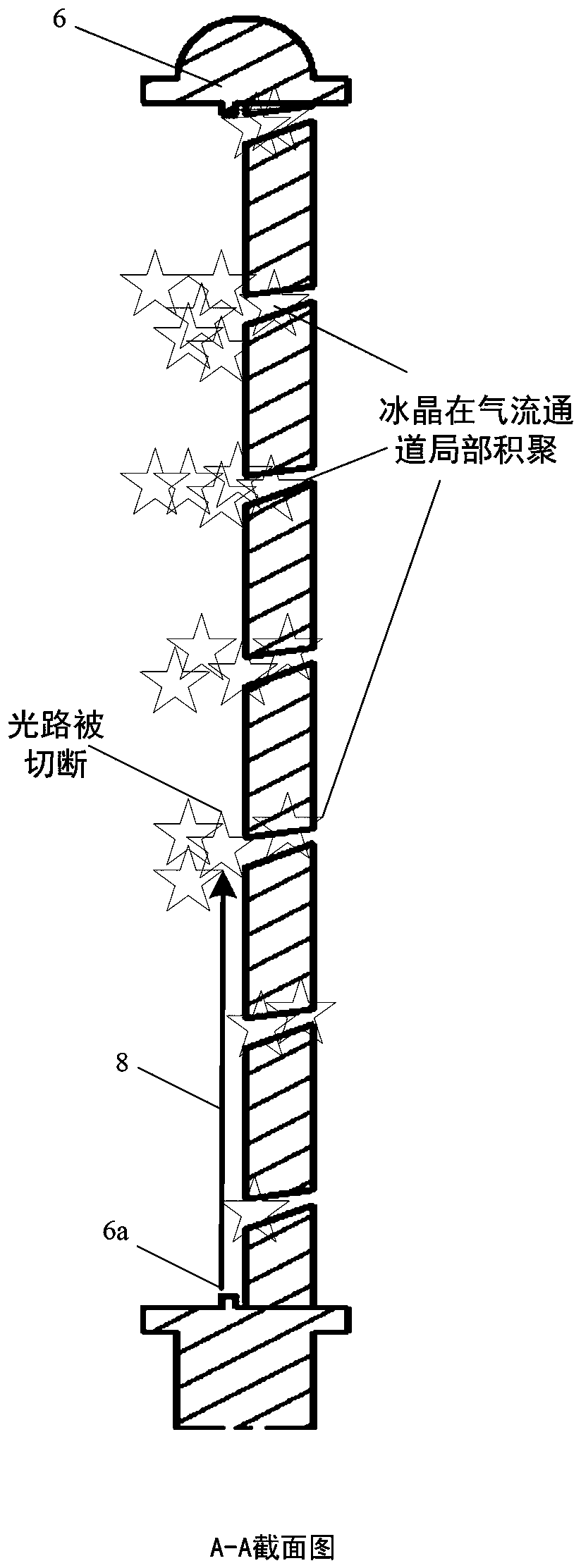
The invention provides an ice crystal detector, which comprises an axially extending ice crystal collecting probe and a detecting device. The ice crystal collecting probe comprises a windward surfaceon one side and a leeward surface opposite to the windward surface, and comprises a rod body, a groove and photoelectric sensors, wherein the groove is positioned on the windward surface and extend inthe axial direction of the rod body, and the photoelectric sensors are arranged at two ends or one end of the rod body. The groove includes an opening and a bottom. The photoelectric sensors form anoptical path in the groove which is spaced from the bottom of the groove for monitoring ice crystals on the bottom of the groove. A controller is connected with the photoelectric sensors and judges whether an ice crystal icing condition exists or not according to the change of the electric signal fed back by the photoelectric sensors. The rod body also comprises a plurality of airflow channels, the inlet of the airflow channels is positioned at the bottom of the groove of the ice crystal collecting probe, and the outlet of the airflow channels is positioned on the leeward surface of the ice crystal collecting probe. The ice crystal detector is simple in structure, high in reliability, easy to achieve and low in electric power consumption, and can be used for detecting whether ice crystal icing conditions exist in the air.

Description

technical field [0001] The invention relates to the field of ice crystal detectors, in particular to an ice crystal detector for detecting whether there is an ice crystal icing condition in the air and a method for the detection. The invention also relates to a mixed-state icing detector for detecting whether ice crystal icing conditions and supercooled water droplets icing conditions exist in the air. Background technique [0002] The icing conditions encountered by aircraft flying in the air include airworthiness provisions 14 CFR Part 25 Appendix C general supercooled water droplet icing conditions (droplet diameter ≤ 50um), 14 CFR Part 25 Appendix O large supercooled water droplet icing conditions (50µm <Water droplet diameter <500µm, called freezing drizzle; water droplet diameter ≥500µm, called freezing rain), and 14 CFR Part 33 Appendix D ice crystal icing conditions. In the present invention, the conventional supercooled water droplets in Appendix C and the la...

Claims


Application Information

Patent Timeline
Patent Type & Authority Applications(China)
IPC IPC(8): B64D15/20G01V8/10
CPCB64D15/20G01V8/10
Inventor 史献林白穆
Owner COMAC
Learn More