One-step composite twisting frame

A twisting machine and footwork technology, applied in spinning machines, continuous winding spinning machines, textiles and papermaking, etc., can solve the problems of unstable balloon tension, uneven yarn twist, blistering, etc. To achieve the effect of stable rotation speed, uniform twist and high pressure

Pending Publication Date: 2019-06-25
HANGZHOU CHANGYI TEXTILE MACHINE
View PDF1 Cites 7 Cited by
  • Summary
  • Abstract
  • Description
  • Claims
  • Application Information

AI Technical Summary

Problems solved by technology

[0003] In view of this, the present invention provides a one-step compound twisting machine. By setting an unwinding device on the top of the primary twisting spindle, it can effectively solve the problem of uneven yarn twist and fluff caused by unstable balloon tension during the yarn twisting process. , foaming and other issues

Method used


Image

  • One-step composite twisting frame
  • One-step composite twisting frame
  • One-step composite twisting frame

Examples


Embodiment 1

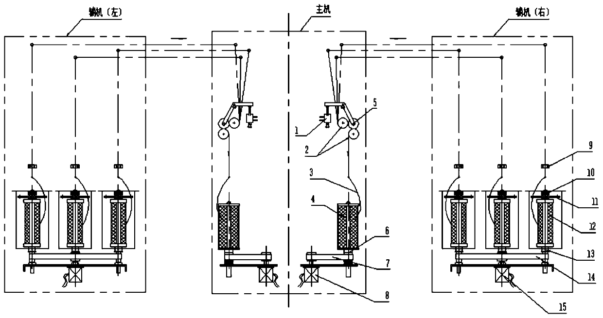
[0026] This embodiment provides a one-step compound twisting machine. By setting the unwinding device, it can effectively solve the problems of uneven twist, fuzzing, foaming, and whitening of PE threads and polyester threads when using one-step twisting machine yarns. Many points, broken ends, inconvenient operation, etc.; this composite twisting machine is suitable for 15-180 strands of PE yarn, 1000D-5000D polyester yarn, etc.

[0027] The one-step compound twisting machine can complete the single-filament twisting and compound twisting process on the same machine at one time.

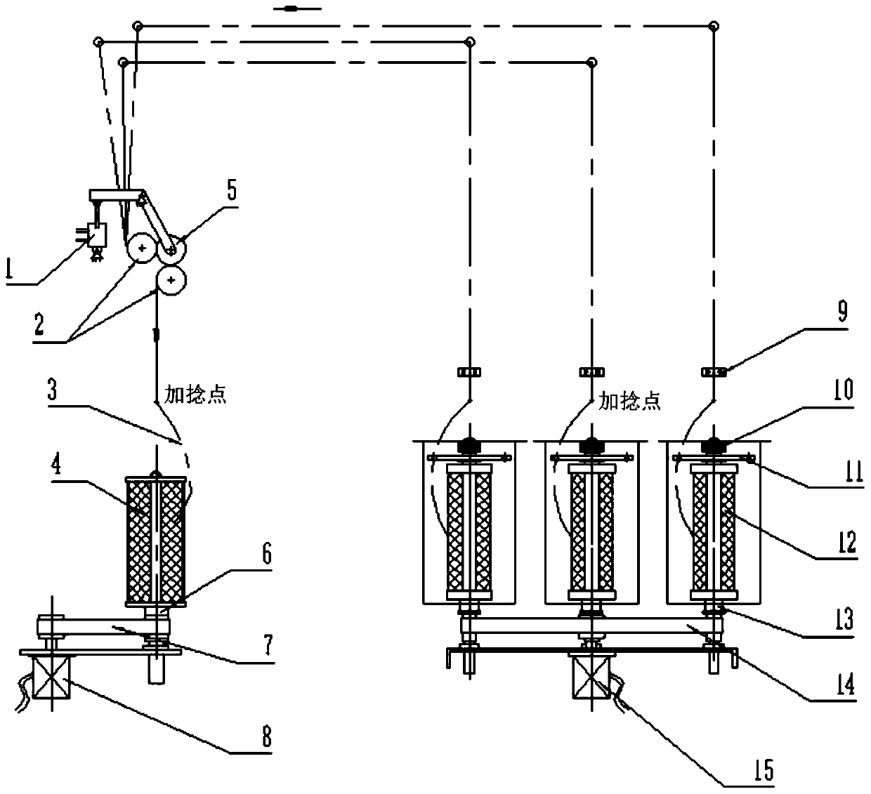
[0028] Such as figure 1 and figure 2 As shown, in this example, the composite twisting machine adopts the layout of the left and right auxiliary machines and the central main machine, and two double twisting mechanisms arranged in parallel are set as the main machine, and a primary twisting mechanism is arranged on the left and right sides of the main machine as the auxiliary machine. , each auxi...

Embodiment 2

[0042] Compared with the above-mentioned embodiment 1, the difference is only in the layout of the initial twisting mechanism and the double twisting mechanism. In this example, the primary twisting mechanism is located above the double twisting mechanism, and the formed composite twister includes an upper structure, a lower structure, and a Roller drive mechanism between structures, such as Figure 6 shown.

[0043] The upper structure includes two primary twisting mechanisms arranged side by side, and the lower structure includes two double twisting mechanisms arranged side by side. The primary twisting mechanism on the left side (right side) of the upper layer structure communicates with the lower layer structure on the left side through the roller transmission mechanism. (right side) is connected to the retwisting mechanism.


PUM


Abstract

The invention provides a one-step composite twisting frame, and belongs to the technical field of textile machinery. By arranging an unwinding device on the top of a first twist spindle, the problemsthat in the yarn twisting process, uneven yarn twist, fuzzing, bubbling and the like are caused by unstable balloon tension can be effectively solved. The one-step composite twisting frame comprises afirst twisting mechanism, a roller transmission structure and the a second twisting mechanism; in the first twisting mechanism, single twisting is conducted through the first twisting spindle, and two or more yarns completing single twisting enter the roller transmission structure for monofilament stranding to form a twisted yarn; the second twisting mechanism is used for second twisting of the twisted yarn; the unwinding device is arranged on the top of the first twist spindle, that is to say, a bracket is additionally arranged in the middle of a twisting zone of the yarns, the size of a balloon formed through high-speed rotation of the yarns in the twisting zone is fixed, the balloon size is basically the same, and the yarn quality problem generated by colliding with other parts cannotbe caused; the problems of yarn fuzzing, bubbling, more white dots, more broken ends and the like of a traditional one-step twisting frame can be effectively solved.

Description

technical field [0001] The invention relates to a textile machine, in particular to a twisting machine, which belongs to the technical field of textile machines. Background technique [0002] In the textile industry, the function of the twisting machine is to combine and twist several raw material (PP) monofilaments into one strand of yarn after initial twisting and double twisting. During the twisting process of the fishing net line (PE), the rotation speed ranges from several thousand to tens of thousands of revolutions per minute, which will form a ring-shaped closed air circle that expands outward. This air circle will be affected by twisting time, winding quality, The influence of bobbin quality and other changes; at present, yarn separators or balloon rings are used to control the change of yarn balloons in the initial twisting, and the tension of the balloons is unstable, which may easily cause the balloons to fail to open or the balloons to be too large to hit the is...

Claims


Application Information

Patent Timeline
Patent Type & Authority Applications(China)
IPC IPC(8): D01H7/86D01H1/241D01H13/04D01H13/16D01H1/22
Inventor 傅吉峰郑守华韩世海方森强
Owner HANGZHOU CHANGYI TEXTILE MACHINE
Why Eureka
Try Eureka