Air purification adsorption type drying machine
An adsorption dryer and air purification technology, applied in chemical instruments and methods, dispersed particle separation, separation methods, etc., can solve the problems of increasing the burden on the adsorption tower, shortening the service life, and damaging the adsorption system, so as to improve the efficiency of adsorption and drying , prolong the service life, and facilitate the handling effect
- Summary
- Abstract
- Description
- Claims
- Application Information
AI Technical Summary
Problems solved by technology
Method used
Image
Examples
Embodiment 1
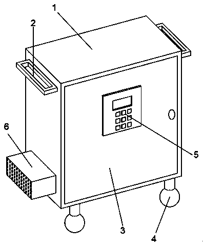
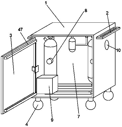
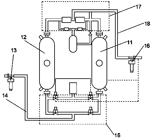
[0035] Embodiment 1: refer to Figure 1-3 ;
[0036] An air-purifying adsorption dryer, comprising an outer shell 1, a handle 2 and a shifting wheel 4, the left and right sides of the outer shell 1 are fixedly connected with handles 2, the bottom of the outer shell 1 is fixed with shifting wheels 4 around, and the left side of the outer shell 1 The lower end of the surface is fixedly equipped with an air intake device 6, and the upper end of the right side surface of the outer shell 1 is provided with an air outlet connecting pipe 10. A monitoring device 47, the mobile monitoring device 47 is electrically connected with the control panel 5, the outer casing 1 is provided with an inner cavity 7, and the inner cavity 7 is fixedly installed with an adsorption drying system 8 and a compression fan 9 respectively, and the compression fan 9 is connected to the air intake The device 6 is connected, and the adsorption drying system 8 includes an A adsorption tower 11 and a B adsorpti...
Embodiment 2
[0038] Embodiment 2: refer to Figure 4 , 5 With 9, the difference in combination with the basis of embodiment 1 is;
[0039] The air intake device 6 includes a suction box body 19, and the front end surface of the suction box body 19 is equidistantly provided with multiple groups of intake screen holes 20, and the upper surface of the front end of the suction box body 19 is provided with an upper slot 21, and the upper slot 21 An upper partition 24 is movable inside, and a side slot 23 is installed in the middle of the left and right sides of the suction box 19, and a side partition 25 is movable inside the side slot 23, and the middle part of the outer end of the side partition 25 is hinged with the pull ring 22 .
[0040] Horizontal sleeve plates 45 are movably socketed on the left and right sides of the upper partition plate 24, and the bottom surface of the horizontal sleeve plate 45 is provided with a positive electrode adsorption layer. There is a negative electrode ...
Embodiment 3
[0042] Embodiment 3: refer to Figure 6-8 , the basis of the embodiment 1 is different in that;
[0043] A wall inner cavity 28 is arranged in the box wall of the suction box body 19, and a side opening device is arranged in the middle of the wall inner cavity 28. The side opening device includes a first shaft seat 26 and a pulley groove 29, and the pulley groove 29 is arranged in the wall inner cavity 28. At the upper and lower ends of the middle part, the upper and lower ends of the first shaft seat 26 are rotationally connected with one end of the connecting shaft 31, the other end of the connecting shaft 31 is fixedly connected with the end surface of the pulley 30, the pulley 30 is slidingly connected with the pulley groove 29, and the first shaft seat 26 is fixedly connected with a second A shaft 27 , the first shaft 27 is rotatably connected to the first shaft sleeve 32 , and the first shaft sleeve 32 is fixedly connected to the inner end of the side partition 25 .
[...
PUM
 Abstract
Description
Claims
Application Information
 - R&D
- Intellectual Property
- Life Sciences
- Materials
- Tech Scout
- Unparalleled Data Quality
- Higher Quality Content
- 60% Fewer Hallucinations
Browse by: Latest US Patents, China's latest patents, Technical Efficacy Thesaurus, Application Domain, Technology Topic, Popular Technical Reports.
© 2025 PatSnap. All rights reserved.Legal|Privacy policy|Modern Slavery Act Transparency Statement|Sitemap|About US| Contact US: help@patsnap.com


