
Novel anti-collision charging pile adopting principle of compressed airflow

A technology of compressed airflow and charging piles, applied in charging stations, electric vehicle charging technology, electric vehicles, etc., can solve the problem of scratches on the body of the anti-collision device, the inability of the driver's rearview mirror to provide collision indication, and the driver's inability to brake in time Measures and other issues to achieve the effect of preventing impact and avoiding scratches

Active Publication Date: 2019-06-28
惠安县锋创商贸有限公司
View PDF9 Cites 2 Cited by
  • Summary
  • Abstract
  • Description
  • Claims
  • Application Information

AI Technical Summary

Problems solved by technology

[0004] In view of the deficiencies in the prior art, the purpose of the present invention is to provide a new type of anti-collision charging pile using the principle of compressed airflow, so as to solve the problem that the anti-collision device is easy to scratch the car body when the charging pile in the prior art adopts mechanical anti-collision. Moreover, it cannot provide collision indication for the driver's rearview mirror in time, resulting in the problem that the driver cannot take braking measures in time

Method used


Image

  • Novel anti-collision charging pile adopting principle of compressed airflow
  • Novel anti-collision charging pile adopting principle of compressed airflow
  • Novel anti-collision charging pile adopting principle of compressed airflow

Examples


Embodiment

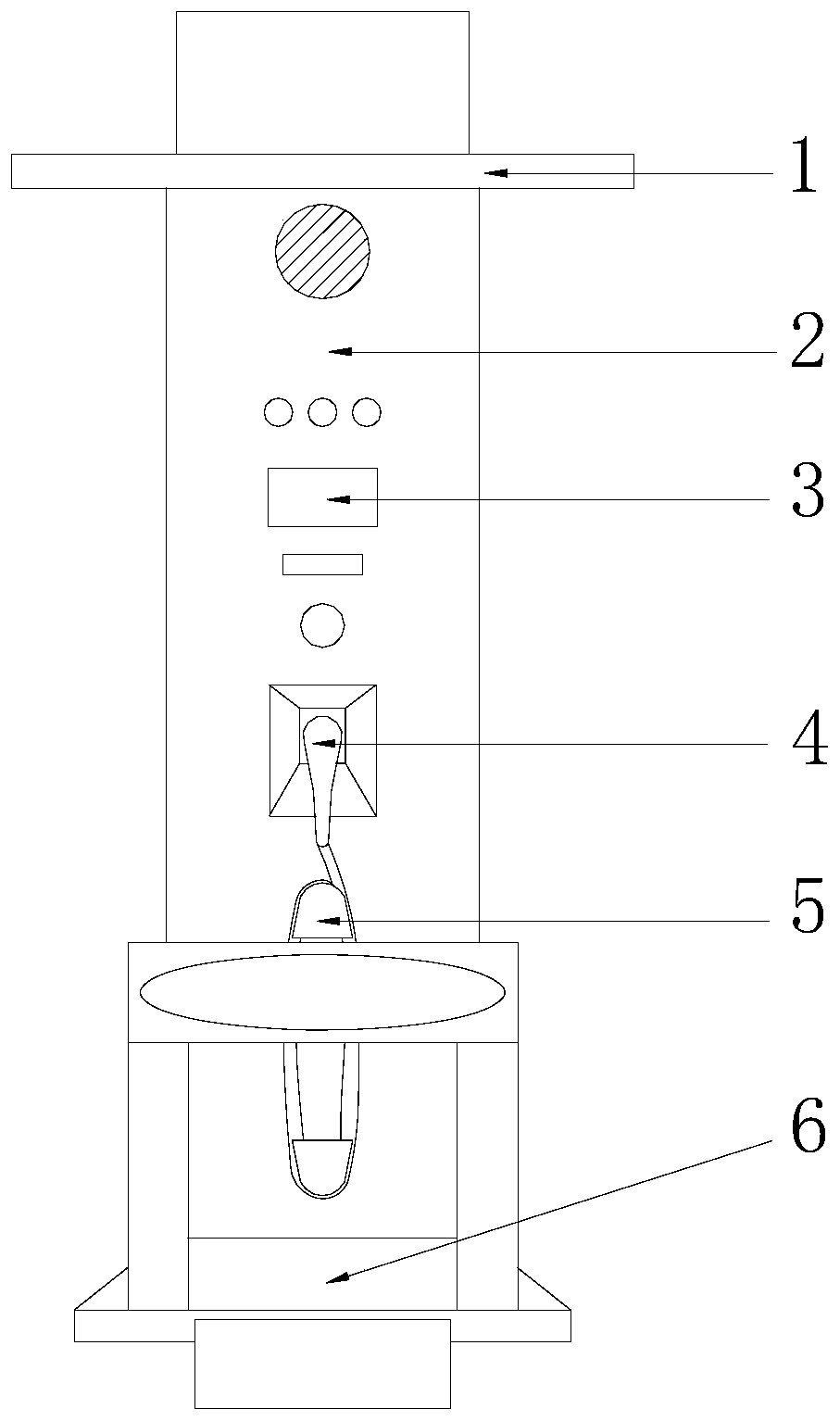
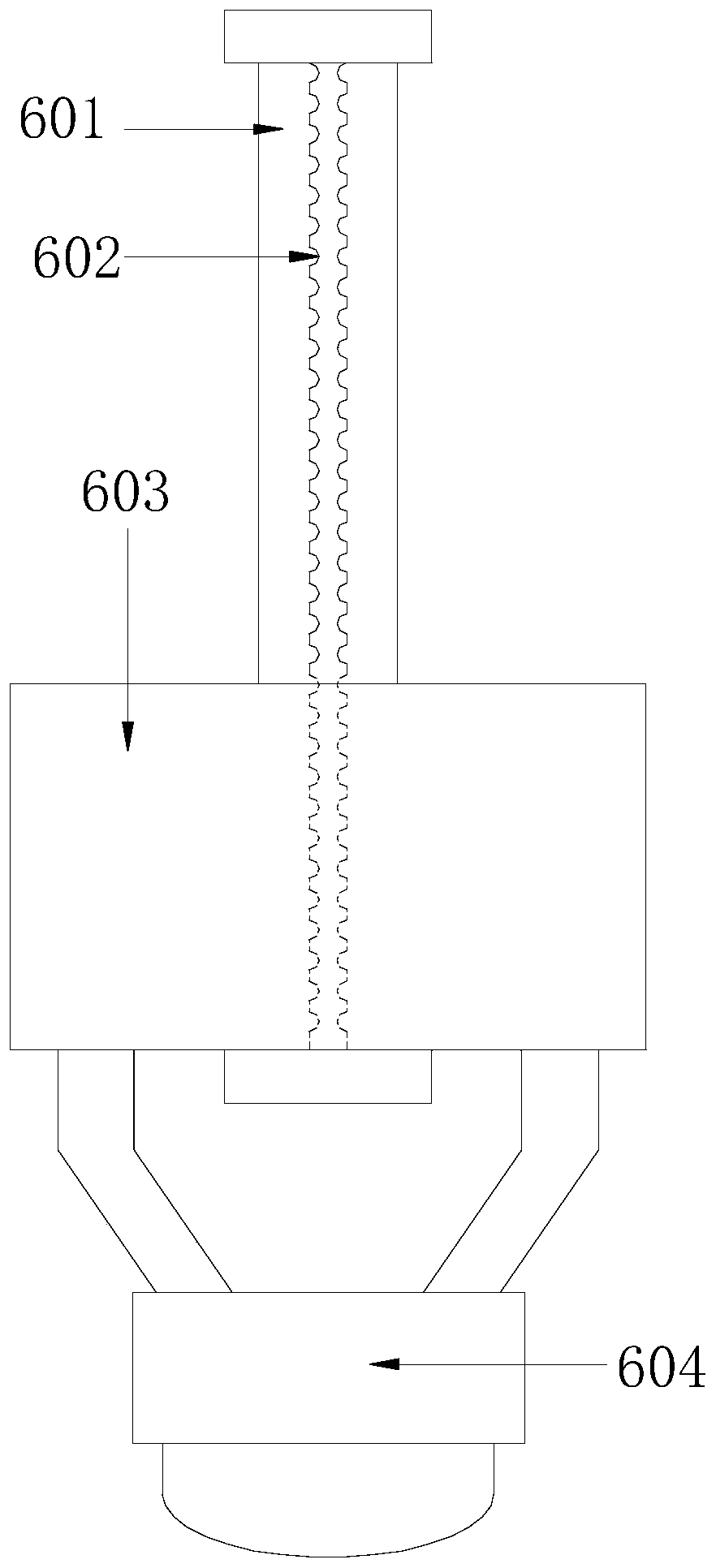
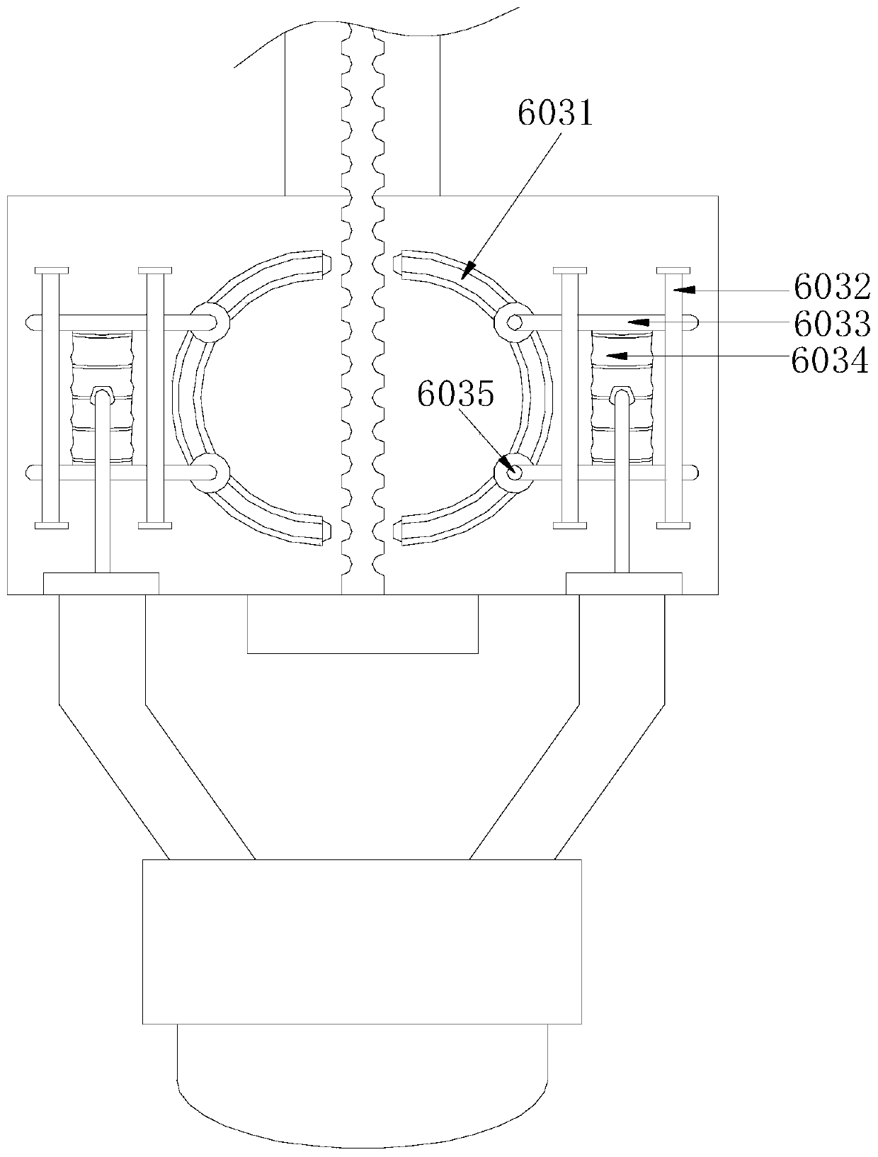
[0028] see Figure 1-Figure 6 , the present invention provides a new type of anti-collision charging pile using the principle of compressed airflow, its structure includes a rain cover 1, a main body of the electric pile 2, a touch panel 3, a charging gun 4, a power cord hanger 5, and an anti-collision mechanism 6 , the bottom of the electric pile host 2 is installed in the middle of the anti-collision mechanism 6 by buckling, the power cord hanger 5 is provided with two, and is installed on the lower end of the electric pile host 2 by welding, the electric pile host 2 The middle part is provided with a groove for installing the charging gun 4. The touch panel 3 has a rectangular structure and is installed on the upper surface of the electric pile host 2 by embedding. The rain shield 1 is installed on the electric pile host by fitting. 2, the top is controlled by the touch panel 3, and then the charging gun 4 is connected to the electric port of the car for charging. The anti-...


PUM


Abstract

The invention discloses a novel anti-collision charging pile adopting the principle of compressed airflow. The novel anti-collision charging pile structurally comprises a rain shield, an electric pilemain machine, a touch panel, a charging gun, two power cord plugging heads and an anti-collision mechanism, wherein the bottom of the electric pile main machine is arranged in the middle of the anti-collision mechanism in a buckling mode; two power cord plugging heads are arranged at the lower end of the electric pile main machine in a welding mode; and a groove for installing the charging gun isarranged in the middle of the electric pile main machine. According to the novel anti-collision charging pile, air in the anti-collision mechanism is compressed by the compressor when collision occurs in reverse, a connecting plate is pneumatically unlocked, and the main machine of the electric pile is driven to move backwards, so that collision to the tail of a vehicle is prevented; a collisionforce to the tail of the vehicle can be reduced by a damage-reducing air bag of the compressor and finally an indicator is driven to rotate and generate friction electricity to indicate; and the novelanti-collision charging pile is used integrally, thus, a driver can be instructed to brake in time, and the tail of the vehicle is effectively prevented from being scratched and damaged by collisioncontact.

Description

technical field [0001] The invention relates to the field of charging piles for new energy vehicles, in particular to a novel anti-collision charging pile using the principle of compressed airflow. Background technique [0002] New energy vehicles use electricity as the driving force, reducing air pollution and saving costs at the same time, so new energy vehicles have become a major trend in the development of the automotive industry. To gain market share and seize the opportunity of market development, charging piles, as the battery life and practical power source of new energy vehicles, have entered the stage of rapid popularization. There are such problems in the existing use process on the market: [0003] When the charging pile of the prior art adopts mechanical anti-collision, the anti-collision device is easy to cause scratches to the vehicle body, and cannot provide an impact indication for the driver's rearview mirror in time, resulting in the driver being unable ...

Claims


Application Information

Patent Timeline
Patent Type & Authority Applications(China)
IPC IPC(8): B60L53/16B60L53/31
CPCY02T90/167Y02T10/70Y02T90/14Y02T10/7072Y02T90/12Y04S30/12
Inventor 黄正金李四张清清刘清水
Owner 惠安县锋创商贸有限公司
Learn More