Novel multifunctional electric rapid cleaning trolley for environmental sanitation

A multi-functional, trolley technology, applied in road cleaning, garbage receptacles, construction, etc., can solve the problems of low work efficiency of sanitation workers, difficulty in picking up garbage, manual picking, etc.

Inactive Publication Date: 2019-06-28
何华
View PDF1 Cites 1 Cited by
  • Summary
  • Abstract
  • Description
  • Claims
  • Application Information

AI Technical Summary

Problems solved by technology

[0003] Existing cleaning trolleys, in order to facilitate the sanitation workers to quickly pick up garbage, usually install a vacuum cleaner on the trolley, but the combination of the trolley and the vacuum cleaner is only suitable for very smooth roads, and encounter some dead ends such as steps or sewer grates. It is inevitable that there will be situations where the garbage is difficult to pick up, especially when the heavy garbage is difficult to be picked up, the sanitation workers still need to pick it up manually, which leads to the low work efficiency of the sanitation workers, so it needs to be improved

Method used


Image

  • Novel multifunctional electric rapid cleaning trolley for environmental sanitation
  • Novel multifunctional electric rapid cleaning trolley for environmental sanitation
  • Novel multifunctional electric rapid cleaning trolley for environmental sanitation

Examples


Embodiment 1

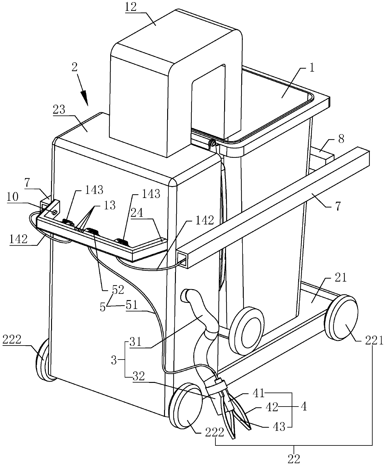
[0053] refer to figure 1 with figure 2 , is a new type of multifunctional electric sanitation fast cleaning trolley disclosed by the present invention, comprising: a car body 2, a trash can 1, a pipe 3, a clamping assembly 4, a power assembly 5, a blowing and sucking device 6, a material guide pipe 12, Power source 11, blowing and sucking switch group 13, side stopper 7, limiter 8 and driving structure.

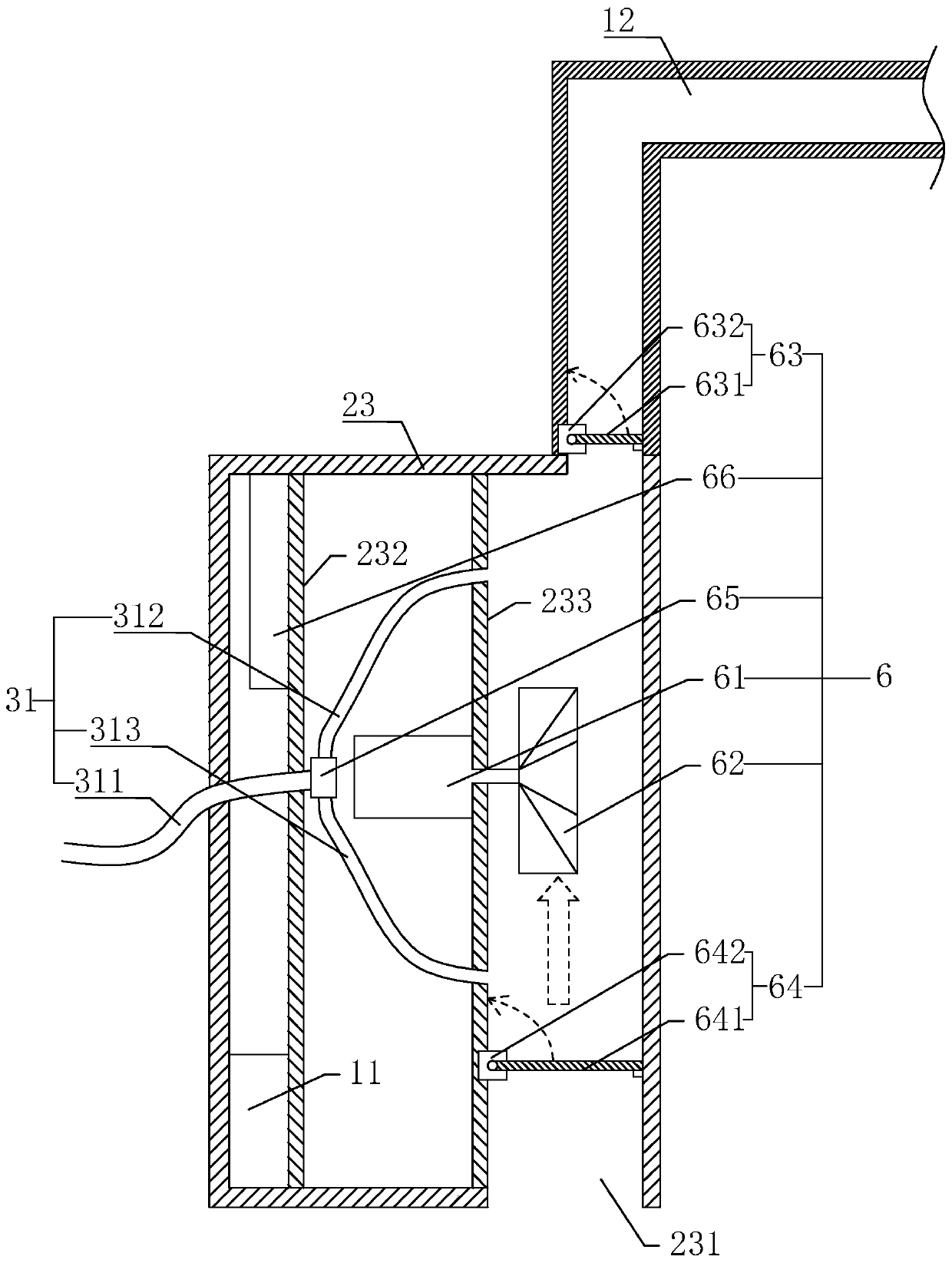
[0054] Car body 2 comprises: base 21, wheel set 22, box body 23 and push handle 24, and wheel set 22 is rotatably installed on base 21, and box body 23 is arranged on base 21 upper surface, and dustbin 1 is placed on base 21 upper surface and is positioned at box. In front of the body 23, the push handle 24 is arranged on the side of the box body 23 away from the trash can 1, and the bottom of the box body 23 is provided with an air inlet 231.

[0055] The pipe 3 includes: a hose 31 and a hard pipe 32, one end of the hose 31 is connected to the box body 23, the other end o...

Embodiment 2

[0086] refer to Figure 5 , is a new type of multifunctional electric sanitation fast cleaning trolley disclosed in the present invention. The difference from Embodiment 1 is that the clamping assembly 4 is specifically a pneumatic finger, and the power assembly 5 includes: an air pipe 53, an air compressor 54 and a control The switch 55 and the air compressor 54 are installed in the casing 23 , the air pipe 53 is connected between the pneumatic finger and the air compressor 54 , the control switch 55 is electrically connected with the air compressor 54 and installed on the push handle 24 .

[0087] After the jaws of the pneumatic fingers are aligned with the garbage to be picked, the air compressor 54 can provide an air source, and the compressed high-pressure gas is injected into the pneumatic fingers through the air pipe 53, thereby driving the pneumatic fingers to work to clamp the garbage. and because sanitation workers generally place their hands on the push handle 24 wh...

Embodiment 3

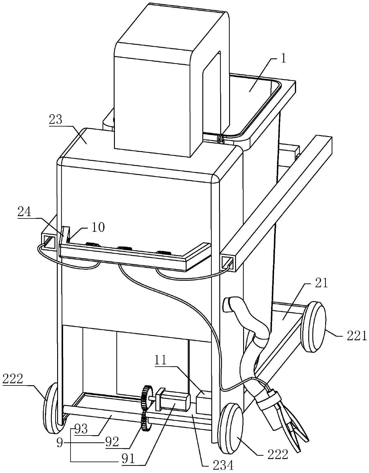
[0089] refer to Image 6 , is a new type of multifunctional electric sanitation fast cleaning trolley disclosed in the present invention. The difference from Embodiment 1 is that the side stopper 7 and the limiter 8 are rotated and assembled, and the driving structure includes: a stepping motor 144 and The operation button 145 and the stepper motor 144 are used to drive the stopper 8 to rotate to realize the state switching. The operation button 145 is electrically connected to the stepper motor 144 and controls the opening and closing of the stepper motor 144 . The stepper motor 144 can set the direction, angle, and speed of its output shaft rotation, so that it can be conveniently used in conjunction with the stopper 8 to realize the state switching of the stopper 8. When the sanitation worker pushes the handcart, his hand is generally placed on the On the push handle 24, so the operation button 145 provided on the push handle 24 is convenient for sanitation workers to press...


PUM


Abstract

The invention relates to a novel multifunctional electric rapid cleaning trolley for environmental sanitation. The novel multifunctional electric rapid cleaning trolley for environmental sanitation ischaracterized by comprising a trolley body, a trash can, a pipeline, a clamping assembly, a power assembly, a blowing suction device, a material guiding pipe, a power source and a blowing suction switch set, wherein the trolley body comprises a base, a wheel set, a box body and a pushing handle, and the bottom of the box body is provided with an air inlet; the pipeline comprises a hose and a hardpipe, the clamping assembly is installed on the peripheral wall of the hard pipe, the power assembly is installed on the pipeline and/or the trolley body, and the power assembly is used for driving the clamping assembly to work; the power source and the blowing suction device are both installed in the box body, the material guiding pipe communicates with the interior of the box body, and the other end of the material guiding pipe stretches into the trash can; the blowing suction switch set controls on-off of the blowing suction device, the blowing suction device blows towards the outside through the pipeline during working, and the blowing suction device sucks trash into the material guiding pipe through the pipeline and/or the air inlet during working. The novel multifunctional electricrapid cleaning trolley for environmental sanitation has the effects that the cost is low, operation is convenient, and the working efficiency of sanitation workers is improved.

Description

technical field [0001] The invention relates to the technical field of sanitation equipment, in particular to a novel multifunctional electric sanitation fast cleaning trolley. Background technique [0002] With the continuous improvement of the quality of life, all kinds of garbage are constantly appearing. Cleaning trolleys are a kind of equipment commonly used by sanitation workers. Sanitation workers can easily push the trolleys to collect garbage everywhere and protect the environment. [0003] Existing cleaning trolleys, in order to facilitate the sanitation workers to quickly pick up garbage, usually install a vacuum cleaner on the trolley, but the combination of the trolley and the vacuum cleaner is only suitable for very smooth roads, and encounter some dead ends such as steps or sewer grates. It is inevitable that there will be situations where garbage is difficult to pick up, especially when heavy garbage is difficult to be picked up, sanitation workers still need...

Claims


Application Information

Patent Timeline
Patent Type & Authority Applications(China)
IPC IPC(8): B65F3/00B65F3/14E01H1/08E01H1/12
Inventor 何华
Owner 何华
Why Eureka
Try Eureka