
Biomass fuel pneumatic conveying device

A biomass fuel and pneumatic conveying technology, which is applied to conveying bulk materials, conveyors, transportation and packaging, etc., can solve the problems of easy flying of materials, difficulty in adding, and unsafe factors.

Active Publication Date: 2021-06-18
重庆和创简一科技有限公司
View PDF0 Cites 0 Cited by
  • Summary
  • Abstract
  • Description
  • Claims
  • Application Information

AI Technical Summary

Problems solved by technology

[0006] To sum up, the present invention provides a biomass fuel pneumatic conveying device, through the improvement of structure and function, to solve the problem that the biomass fuel needs stable material addition during combustion, and it is not easy to overdose, but because the quality of the biomass particles itself is relatively low It is light, which makes it difficult to add, and the way of blowing the material with the blower, the material is easy to fly, causing the problem of unsafe factors

Method used


Image

  • Biomass fuel pneumatic conveying device
  • Biomass fuel pneumatic conveying device
  • Biomass fuel pneumatic conveying device

Examples


Embodiment Construction

[0029] Embodiments of the present invention will be further described in detail below in conjunction with the accompanying drawings and examples. The following examples are used to illustrate the present invention, but should not be used to limit the scope of the present invention.

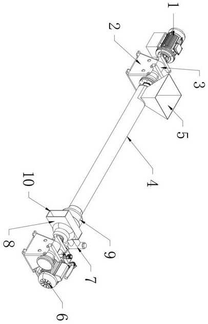
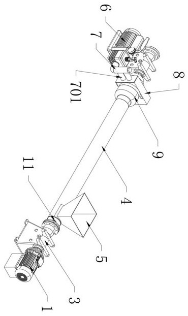
[0030] Please refer to Figure 1 to Figure 8 .

[0031] In order to solve the existing problems in the biomass fuel pneumatic conveying device in the prior art, the biomass fuel needs to be added stably when burning, and it is not easy to overdo it. However, due to the light weight of the biomass particles, it is difficult to add, and the blower blowing method is adopted. , the material is easy to fly, causing the problem of unsafe factors. The present invention proposes a biomass fuel pneumatic conveying device, which is used to carry out technical innovation on the biomass fuel pneumatic conveying device, including: pump 1, pedestal 2, coupling 3. Conveying bin 4, feeding hopper 5, air compres...


PUM


Abstract

The invention provides a biomass fuel pneumatic conveying device, which includes a pump, a turbine blade and a deflector; a shaft coupling is installed at the right end of the pump; Rotationally connected to the bearing seat of the pedestal at the right end, and the connection between the coupling and the left end of the conveying shaft is also fixed and downwardly installed with a pedestal; the outer sheath of the conveying shaft between the two pedestals is covered with a cylindrical The feeding bin; the top of the left end of the feeding bin is fixed with a feeding hopper that is wide at the top and narrow at the bottom. The invention provides a biomass fuel pneumatic conveying device, the conveying paddles and turbine blades are arranged, and the conveying shaft is provided with two sets of helical conveying paddles to improve the conveying efficiency of biomass particles and further prevent the material from returning , In addition, the diameter of the booster bin is larger than that of the delivery bin, so that the booster bin forms a larger inner cavity space, which is convenient for the material to advance from the edge to the right when the turbine blade rotates.

Description

technical field [0001] The present invention relates to the technical field of biomass power generation, and more specifically relates to a biomass fuel pneumatic conveying device. Background technique [0002] Pneumatic conveying, also known as airflow conveying, uses the energy of airflow to convey granular materials along the direction of airflow in a closed pipeline. It is a specific application of fluidization technology. The main characteristics of pneumatic conveying are large conveying volume and long conveying distance. The conveying speed is high; it can be loaded in one place and then unloaded in multiple places. [0003] Through the technical analysis of the biomass fuel pneumatic conveying device by the technicians, it is found that the biomass fuel needs stable material addition during combustion, and it is not easy to overdose. In this way, the material is easy to fly, resulting in unsafe factors. [0004] Therefore, the existing biomass fuel pneumatic conve...

Claims


Application Information

Patent Timeline
Patent Type & Authority Patents(China)
IPC IPC(8): B65G53/58B65G53/66B65G53/48B65G53/40
Inventor 赵瑞霞
Owner 重庆和创简一科技有限公司
Learn More