


Quick Research
Generate reliable direction feasibility study reports for your R&D in just a few steps.

Technical Q&A
Discover and master advanced knowledge NOW. Basics, ideas, possibilities, all at once.

Find Solutions
As an expert in R&D theories, this can generate solutions to your technical problems instantly.

Evaluate Feasibility
Analyze your overall solution with one click, know your potential R&D risks in advance.

Monitor Landscape
Get weekly tech updates, stay abreast of the latest tech innovations and key insights.
Engine cooling system
A technology for engine cooling and bonnet assembly, which is applied in the direction of engine cooling, engine components, machines/engines, etc. It can solve the problems of slow response, complicated heating resistor winding process, low pass rate, etc., and achieve the effect of life extension
- Summary
- Abstract
- Description
- Claims
- Application Information
AI Technical Summary
Problems solved by technology
Method used
Image

Examples
Embodiment 1
[0024] as the picture shows:
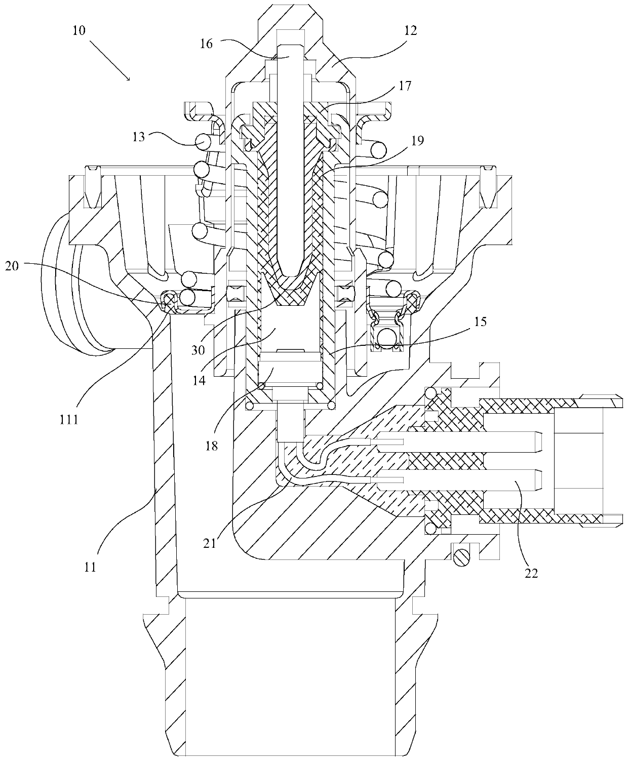
[0025] An engine cooling system, the engine cooling system includes an electronic controller, the electronic controller includes a three-way valve body, an electronic sensor, a valve cover assembly, an elastic member, a heating plate, a copper body and a push rod; the three There is a valve seat inside the main body of the through valve, the electronic sensor is connected to the controller, the controller adopts a low-power processor, a sealing member is arranged inside the valve cover assembly, and a convex body is arranged on the sealing member structure; the valve cover assembly abuts against the valve seat, and the elastic body pushes the valve cover assembly toward the valve seat; the copper body is fixed on the three-way valve body and relatively to the valve The cover assembly is arranged on the same side of the valve seat; a sealed chamber is provided inside the copper body, the push rod is slidably inserted into the copper body, and one ...
Embodiment 2
[0038] Such as figure 1 As shown, an engine cooling system includes an electronic controller 10, and the electronic controller 10 includes: a three-way valve main body 11, a valve cover assembly 12, and an elastic member 13 (in this embodiment, a Spring), heating plate 14, copper body 15 and push rod 16.
[0039] A valve seat 111 is disposed inside the three-way valve body 11 , the valve cover assembly 12 abuts against the valve seat 111 , and the elastic body pushes the valve cover assembly 12 toward the valve seat 111 .
[0040] The copper body 15 is fixed on the three-way valve main body 11 and on the same side of the valve seat 111 relative to the valve cover assembly 12 .
[0041] The inside of the copper body 15 is provided with a sealed chamber, the push rod 16 is slidably inserted into the copper body 15, one end of the push rod 16 is inserted into the sealed chamber, the other end of the push rod 16 One end exposes the copper body 15 and faces the valve cover assemb...
PUM
| Property | Measurement | Unit |
|---|---|---|
| Resistance | aaaaa | aaaaa |
| Thickness | aaaaa | aaaaa |
Abstract
Description
Claims
Application Information
 - R&D Engineer
- R&D Manager
- IP Professional
- Industry Leading Data Capabilities
- Powerful AI technology
- Patent DNA Extraction
Browse by: Latest US Patents, China's latest patents, Technical Efficacy Thesaurus, Application Domain, Technology Topic, Popular Technical Reports.
© 2024 PatSnap. All rights reserved.Legal|Privacy policy|Modern Slavery Act Transparency Statement|Sitemap|About US| Contact US: help@patsnap.com