High-PSRR (power supply rejection ratio) band-gap reference circuit with voltage pre-stabilizing structure

A high power supply rejection ratio, reference circuit technology, applied in the direction of adjusting electrical variables, control/regulation systems, instruments, etc., can solve the problems of poor power supply rejection, affecting chip performance, etc., to improve matching, improve the impact of PSR damage, The effect of improving loop stability

Active Publication Date: 2019-06-28
UNIV OF ELECTRONICS SCI & TECH OF CHINA
View PDF6 Cites 19 Cited by
  • Summary
  • Abstract
  • Description
  • Claims
  • Application Information

AI Technical Summary

Problems solved by technology

[0003] Existing traditional reference sources usually use the addition of the negative temperature coefficient of the base-emitter voltage Vbe of the bipolar transistor and the voltage of the positive temperature coefficient to eliminate the first-order temperature in the bandgap reference source. Although the bandgap reference source It can generate a first-order temperature-independent reference voltage, but its power supply rejection (PSR) is generally poor, which seriously affects the performance of the chip

Method used


Image

  • High-PSRR (power supply rejection ratio) band-gap reference circuit with voltage pre-stabilizing structure
  • High-PSRR (power supply rejection ratio) band-gap reference circuit with voltage pre-stabilizing structure
  • High-PSRR (power supply rejection ratio) band-gap reference circuit with voltage pre-stabilizing structure

Examples


Embodiment Construction

[0036] The technical solution of the present invention will be described in detail below in conjunction with the accompanying drawings and specific embodiments.

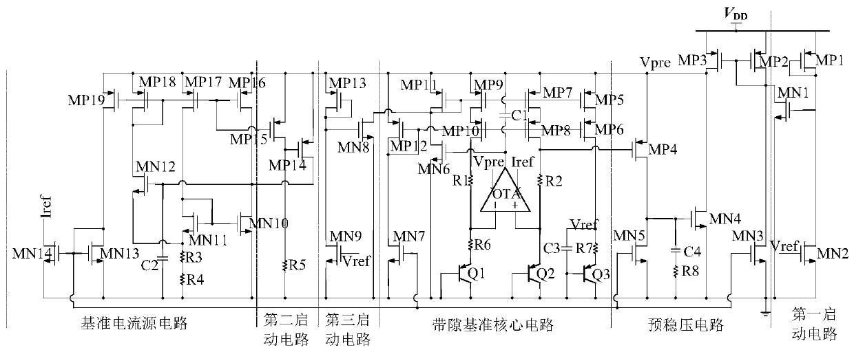
[0037] The present invention proposes a high power supply rejection ratio bandgap reference circuit with a pre-regulated voltage structure, including a first start-up circuit, a second start-up circuit, a third start-up circuit, a pre-regulated voltage circuit, a reference current source circuit and a bandgap reference core circuit, wherein the pre-stabilizing circuit is used to generate the partial voltage Vpre to supply power for the second start-up circuit, the third start-up circuit, the reference current source circuit and the bandgap reference core circuit; as figure 1As shown, the pre-regulator circuit includes a second PMOS transistor MP2, a third PMOS transistor MP3, a fourth PMOS transistor MP4, a third NMOS transistor MN3, a fourth NMOS transistor MN4, a fifth NMOS transistor MN5, a fourth capacitor C4 and ...


PUM


Abstract

A high-PSRR (power supply rejection ratio) band-gap reference circuit with a voltage pre-stabilizing structure comprises a first starting circuit, a second starting circuit, a third starting circuit,a voltage pre-stabilizing circuit, a reference current source circuit and a band-gap reference core circuit, wherein the first starting circuit, the second starting circuit and the third starting circuit are used for starting the voltage pre-stabilizing circuit, the reference current source circuit and the band-gap reference core circuit respectively; the voltage pre-stabilizing circuit is used for generating local voltage to supply power to the second starting circuit, the third starting circuit, the reference current source circuit and the band-gap reference core circuit to realize the effect of inhibiting power ripples; the reference current source circuit is used for generating reference current, and the band-gap reference core circuit generates reference voltage. Through technologiessuch as a common-source and common-gate current mirror of the band-gap reference core circuit, a feedforward path at the output end of an operational amplifier, a third branch added to the reference current source circuit, an RC low-pass filtering circuit connected to an output end of a reference source in series and the like, the PSRR of the band-gap reference circuit is effectively improved.

Description

technical field [0001] The invention belongs to the technical field of electronic circuits and relates to a bandgap reference circuit with a high power supply rejection ratio and a pre-stabilized voltage structure. Background technique [0002] As the core module of the analog circuit, the bandgap reference circuit provides a reference voltage for the analog circuit that does not change with changes in power supply voltage, process and temperature. Its performance determines the performance and function realization of the entire analog circuit and even the entire chip. In a mixed-signal system, because the high-frequency coupling noise of the digital circuit module can be fed through to the analog circuit module through the power supply, ground and analog-digital interface, it will have a fatal impact on the sensitive analog circuit, so the power supply ripple of the bandgap reference Wave noise suppression ability has attracted more and more attention. [0003] Existing tr...

Claims


Application Information

Patent Timeline
Patent Type & Authority Applications(China)
IPC IPC(8): G05F1/575G05F1/567
Inventor 李泽宏胡任任杨尚翰洪至超仪梦帅
Owner UNIV OF ELECTRONICS SCI & TECH OF CHINA
Why Eureka
Try Eureka