Imaging shooting system and method based on filter optical wheel

A shooting system and shooting method technology, applied in the field of image processing, can solve the problems of complex structure of a single camera, affecting image quality, light intensity loss, etc., and achieve the effects of avoiding light intensity loss, avoiding image dislocation, and improving image quality

Pending Publication Date: 2019-06-28
WUHAN HONGRUIDA INFORMATION TECH CO LTD
View PDF6 Cites 5 Cited by
  • Summary
  • Abstract
  • Description
  • Claims
  • Application Information

AI Technical Summary

Problems solved by technology

[0006] In the current imaging and shooting system, the structure of the light splitting method of a single camera is complex and the volume is too large. The use of gratings or prisms for light splitting is likely to cause loss of light intensity and affect image quality. However, the multi-camera solution has synchronization problems during image synthesis, which is likely to cause image synthesis errors. dislocation

Method used


Image

  • Imaging shooting system and method based on filter optical wheel
  • Imaging shooting system and method based on filter optical wheel
  • Imaging shooting system and method based on filter optical wheel

Examples


Embodiment 1

[0051] An embodiment of the present invention provides an imaging and shooting system based on a filter light wheel, which can be used to allow optical signals of different frequencies to pass through and form images, and then synthesize the images corresponding to different optical signals into required images or videos according to requirements.

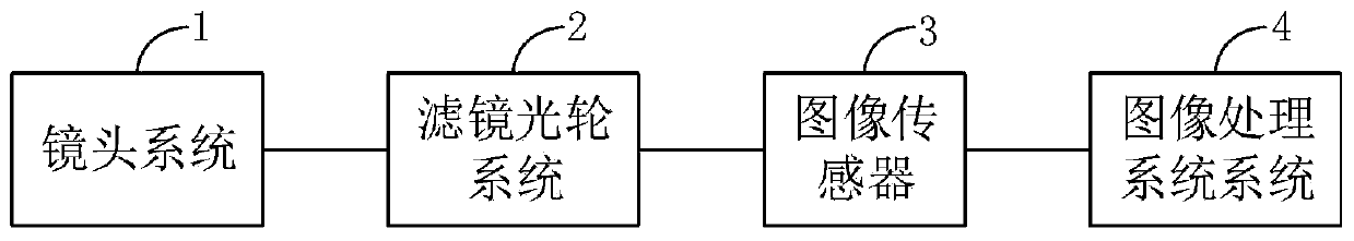
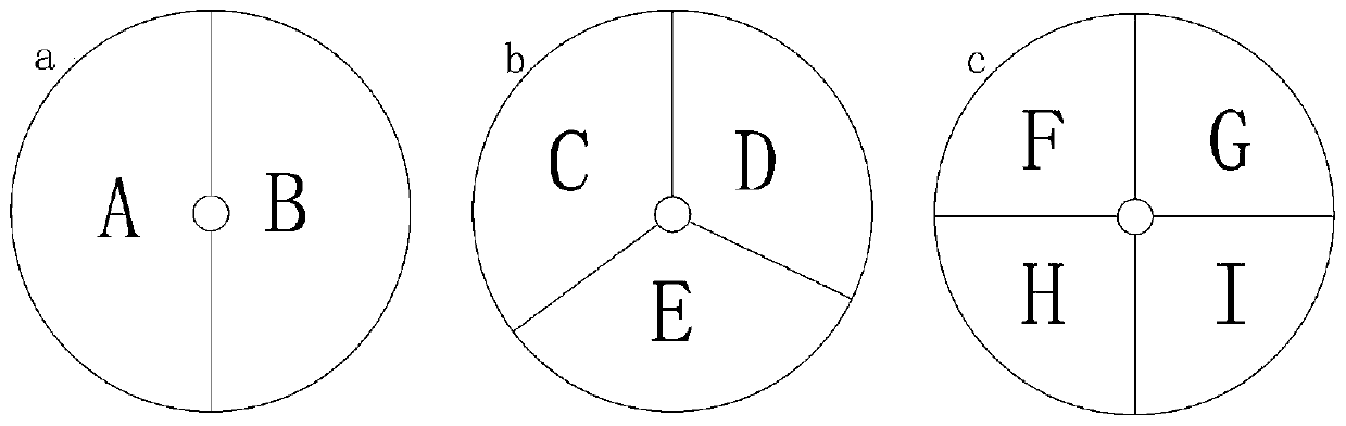
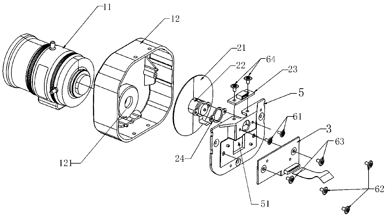
[0052] Such as figure 1 As shown, the imaging and shooting system provided by the embodiment of the present invention includes a lens system 1 , a filter wheel system 2 , an image sensor 3 and an image processing system 4 . combine figure 2 and image 3 , the filter light wheel system 2 includes a rotatable filter light wheel 21, the filter light wheel 21 is divided into at least two fan-shaped areas along the circumferential direction, and different areas are respectively subjected to different surface coatings, thereby forming different The optical filter is used to pass light signals of different frequencies, that is, each ar...

Embodiment 2

[0076] On the basis of the above-mentioned embodiment 1, the embodiment of the present invention also provides an imaging and shooting method based on a filter light wheel, which can be completed by using the imaging and shooting system described in embodiment 1. Such as Figure 5 As shown, the imaging and shooting method provided in the embodiment of the present invention specifically includes:

[0077] Step 10, during the rotation of the filter light wheel, different areas enter the optical path in turn, and the filtered light is divided into optical signals of different frequencies to pass through.

[0078] With reference to Embodiment 1, light first enters the lens system 1, and then reaches the filter wheel 21 along the optical path. The filter light wheel 21 is connected to the motor 22, and then rotates under the drive of the motor 22, so that different areas of the filter light wheel 21 enter the optical path in turn according to the order of arrangement, and then the...

Embodiment 3

[0122] On the basis of the above-mentioned embodiment 1 and embodiment 2, the embodiment of the present invention also provides an imaging device based on a filter light wheel, such as Figure 11 Shown is a schematic diagram of the device architecture of the embodiment of the present invention. The imaging and shooting device based on the filter light wheel in this embodiment includes one or more processors 71 and memory 72 . in, Figure 11 A processor 71 is taken as an example.

[0123] The processor 71 and the memory 72 may be connected via a bus or in other ways, and connection via a bus is taken as an example in FIG. 11 .

[0124] The memory 72, as a non-volatile computer-readable storage medium of the imaging and shooting method based on the filter light wheel, can be used to store non-volatile software programs, non-volatile computer-executable programs and modules, as in the embodiment The imaging shooting method based on the filter light wheel in 1. The processor 7...


PUM


Abstract

The invention relates to the technical field of image processing, in particular to an imaging shooting system and method based on a filter optical wheel, and the method comprises the steps: enabling different areas to enter an optical path in turn in the rotation process of the filter optical wheel, filtering light rays, and dividing the filtered light rays into optical signals with different frequencies to pass through; wherein the optical signals with different frequencies are imaged on the image sensor respectively; and synthesizing the images corresponding to the optical signals with different frequencies to obtain a required image. The filter optical wheel is divided into at least two regions along the circumferential direction, and different regions are respectively subjected to different surface coating and are used for allowing optical signals with different frequencies to pass through. By means of the imaging shooting system and method, optical signals with different frequencies can be filtered through the filter and reach the image sensor to be imaged, and finally the optical signals are synthesized into needed images or videos, so that light intensity loss caused by grating or lens light splitting is avoided, imaging details are increased, the synchronization effect is guaranteed, and the image quality is effectively improved.

Description

【Technical field】 [0001] The present invention relates to the technical field of image processing, in particular to an imaging and shooting system and method based on a filter light wheel. 【Background technique】 [0002] With the development of national economy, video surveillance system, as the core part of the development of security field, has become a necessity to ensure social stability and public and private property security on a global scale. With the development of industry and network, video surveillance related technologies have also made great progress, but the technology of the camera itself still has certain deficiencies. The current popular cameras cannot meet the needs of all-weather and complex lighting conditions. Although digital image processing technology can provide certain supplements and enhancements to the imaging effect of the camera, only the technical upgrade of the camera itself can fundamentally meet various complex lighting conditions. Under t...

Claims


Application Information

Patent Timeline
Patent Type & Authority Applications(China)
IPC IPC(8): H04N5/225H04N5/232G03B11/00G02B26/00
Inventor 朱光喜
Owner WUHAN HONGRUIDA INFORMATION TECH CO LTD
Why Eureka
Try Eureka