

Conveying and rotating device for double-sided glass coating
A rotating device and double-sided glass technology, applied in sputtering coating, ion implantation coating, vacuum evaporation coating, etc., can solve the problems of waste of manpower, high production cost, poor decoration, etc., and achieve coherent and automatic process procedures High degree, the effect of improving the yield rate
- Summary
- Abstract
- Description
- Claims
- Application Information
AI Technical Summary
Problems solved by technology
Method used
Image

Examples
Embodiment Construction
[0023] Specific embodiments of the present invention will be described in detail below in conjunction with the accompanying drawings. It should be understood that the specific embodiments described here are only used to illustrate and explain the present invention, and are not intended to limit the present invention.
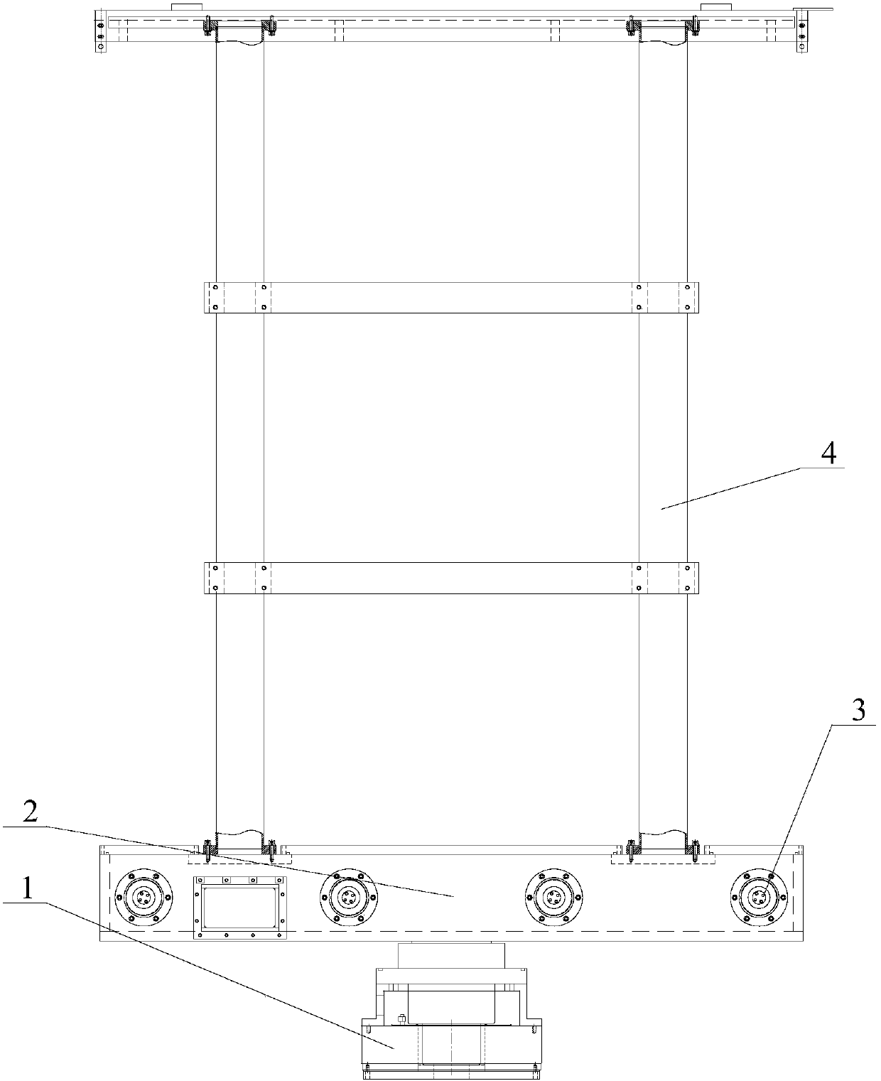
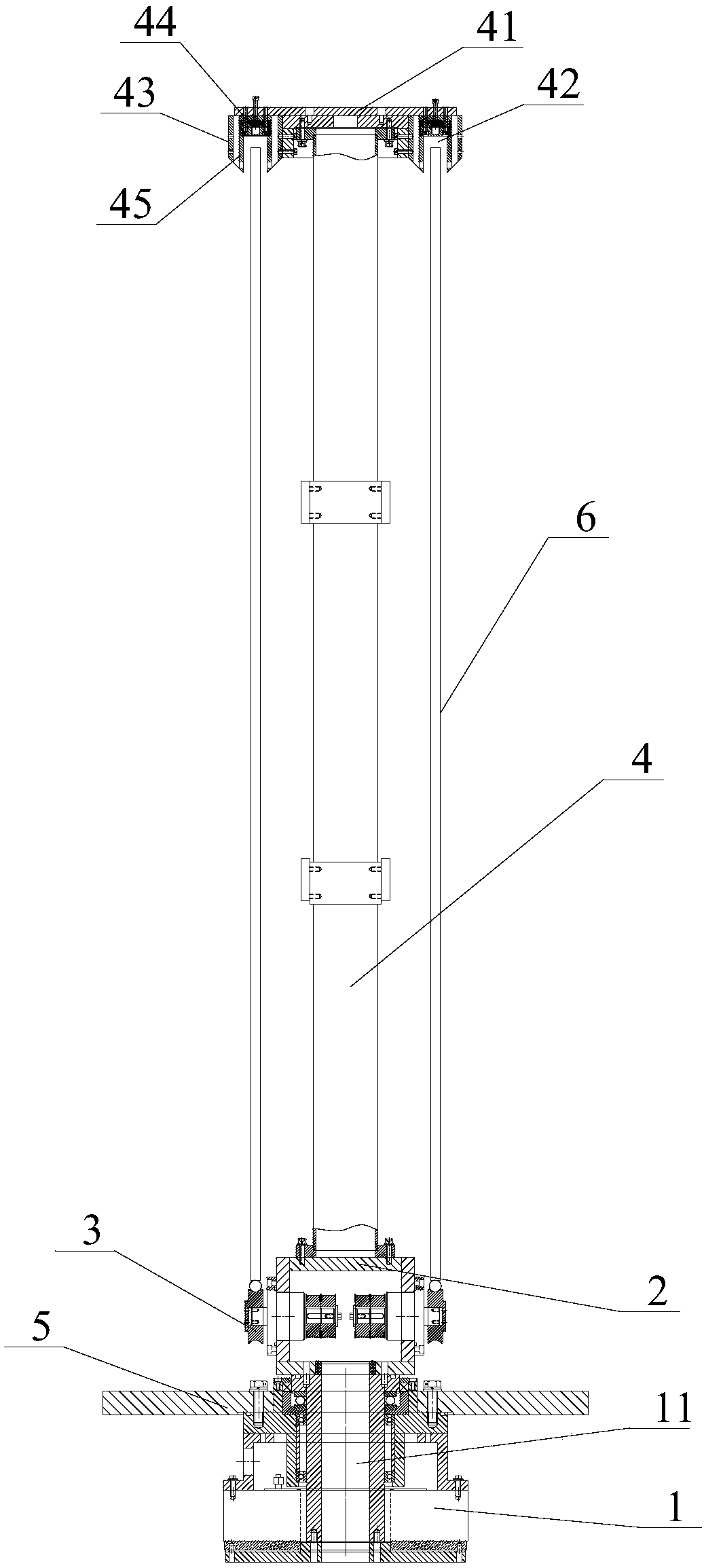
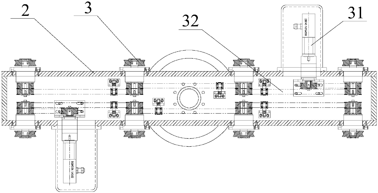
[0024] Figure 1 to Figure 3 It shows an embodiment of the conveying and rotating device for double-sided glass coating of the present invention, the conveying and rotating device includes a rotating assembly, a conveying assembly and a supporting assembly, and the rotating assembly includes a rotating motor 1 and a rotating frame 2, and the rotating motor 1 is installed on Below the bottom plate 5 of the process chamber of the coating production line, the rotating frame 2 is located above the bottom plate 5, and the rotating motor 1 is fixedly connected to the rotating frame 2, and drives the rotating frame 2 to rotate; the transmission component includes a plu...
PUM
 Abstract
Description
Claims
Application Information