Separation structure of leg wire with safety battery module and electronic detonator body

A battery module and separation structure technology, applied in the direction of weapon accessories, fuzes, offensive equipment, etc., can solve problems such as low efficiency, cumbersome production of digital detonators, and large waste of social public resources, so as to facilitate management and control and reduce the effective working length , Conducive to the effect of safe storage

Pending Publication Date: 2019-07-02
张锐
View PDF6 Cites 2 Cited by
  • Summary
  • Abstract
  • Description
  • Claims
  • Application Information

AI Technical Summary

Problems solved by technology

[0002] Digital electronic detonators are generally powered by capacitors. Due to the limitation of the size of the detonators, the capacity of the capacitors is limited; in the process of blasting, after the main communication line is blown, the work of the digital electronic detonators is only powered by the energy stored in the capacitor of the energy storage element. work, and then the seismic wave, shock wave, ultrasonic vibration, electromagnetic wave, etc. generated by the explosives driven by the previous detonator caused the MCU of the subsequent electronic detonator to shut down or temporarily lose its working ability (the capacitor is in the process of continuous discharge), and the seismic wave that has been blasted, After the shock wave, ultrasonic vibration, and electromagnetic wave, even if the MCU returns to normal, the energy storage of the capacitor can no longer support the work of the MCU, or can support the work of the MCU, but the energy of the capacitor is not enough to support the energy required for the ignition charge, so the traditional electronic Detonators often fail to explode
[0003] The current digital electronic detonator products all have a structure that integrates the foot wire and the digital electronic detonator. This structure is cumbersome and inefficient for digital detonator manufacturers, and requires a larger inventory space for product storage, transportation, and control. Social public Large waste of resources

Method used


Image

  • Separation structure of leg wire with safety battery module and electronic detonator body
  • Separation structure of leg wire with safety battery module and electronic detonator body
  • Separation structure of leg wire with safety battery module and electronic detonator body

Examples


Embodiment Construction

[0028] In order to make the object, technical solution and advantages of the present invention clearer, the present invention will be further described in detail below in conjunction with the accompanying drawings and embodiments. It should be understood that the specific embodiments described here are only used to explain the present invention, not to limit the present invention.

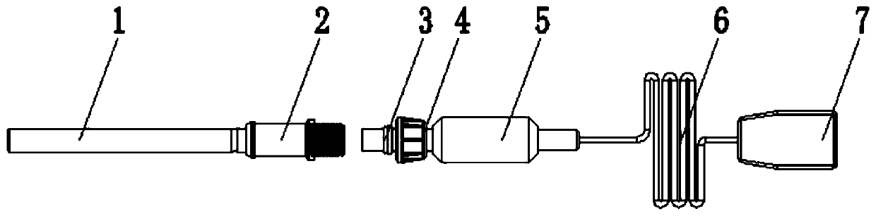
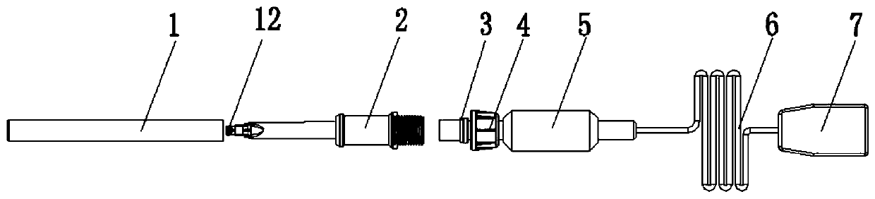
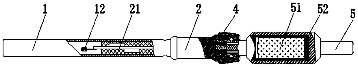
[0029] refer to Figure 1-6 , a separation structure with a safety battery module foot wire and a detonator tube body, including an electronic chip housing 2, a PCBA21 of a digital electronic chip is embedded in the electronic chip housing 2, and a basic detonator 1 is provided at one end of the electronic chip housing 2 One end of the basic detonator 1 away from the electronic chip housing 2 is provided with a wire head 5, and the end of the wire head 5 away from the electronic chip housing 2 is fixedly connected with a communication wire 6, and the end of the communication wire 6 far away from th...


PUM


Abstract

The invention discloses a separation structure of a leg wire with a safety battery module and an electronic detonator body. An intelligent digital electronic detonator adopts the separation structureof the leg wire and an ignition part of an electronic detonator chip. The separation structure comprises an electronic chip shell, and a PCBA of a digital electronic chip is embedded in the electronicchip shell. A base detonator is disposed at one end of the electronic chip shell, and a quick leg wire head is disposed at the end, away from the base detonator, of the electronic chip shell. The quick leg wire head is provided with the safety battery module, and a communication wire is fixedly connected to the end, away from the electronic chip shell, of the leg wire head. A quick clip is fixedly connected to the end, away from the leg wire head, of the communication wire. The separation structure solves the problem of failure detonation of a traditional digital electronic detonator in blasting operation of a roadway, a shallow hole, a tunnel and the like, safe storage and production management and control are facilitated, the management and control over the logistics is further facilitated, and the national popularization requirements for digital electronic detonators are met.

Description

technical field [0001] The invention belongs to the technical field of civil explosive equipment, and in particular relates to an intelligent digital electronic detonator which utilizes the separation structure of a safety battery module leg line and a detonator tube body, thereby realizing continuous energy to ensure the intelligent operation of a digital electronic chip. Background technique [0002] Digital electronic detonators are generally powered by capacitors. Due to the limitation of the volume of the detonators, the capacity of the capacitors is limited. work, and then the seismic wave, shock wave, ultrasonic vibration, electromagnetic wave, etc. generated by the explosives driven by the previous detonator caused the MCU of the subsequent electronic detonator to shut down or temporarily lose its working ability (the capacitor is in the process of continuous discharge), and the seismic wave that has been blasted, After the shock wave, ultrasonic vibration, and elect...

Claims


Application Information

Patent Timeline
Patent Type & Authority Applications(China)
IPC IPC(8): F42C19/12
CPCF42C19/12
Inventor 张锐
Owner 张锐
Why Eureka
Try Eureka