
Anterior radio frequency (RF) coil array for a magnetic resonance imaging (MRI) system

A technology of magnetic resonance imaging and coil array, which is applied in the directions of magnetic resonance measurement, control/adjustment system, application, etc., and can solve problems such as rigidity, unsatisfactory coil size positioning, and uncomfortable feeling of imaging subjects

Active Publication Date: 2019-07-02
GENERAL ELECTRIC CO
View PDF13 Cites 0 Cited by
  • Summary
  • Abstract
  • Description
  • Claims
  • Application Information

AI Technical Summary

Problems solved by technology

However, conventional RF coils tend to be bulky, rigid and configured to remain in a fixed position relative to other RF coils in the array
This bulk and lack of flexibility often prevents the RF coil loop from coupling optimally with the desired anatomy and can be uncomfortable for the imaging subject
Additionally, coil-to-coil interactions result in suboptimal sizing and / or positioning of these coils from a coverage or imaging acceleration perspective

Method used


Image

  • Anterior radio frequency (RF) coil array for a magnetic resonance imaging (MRI) system
  • Anterior radio frequency (RF) coil array for a magnetic resonance imaging (MRI) system
  • Anterior radio frequency (RF) coil array for a magnetic resonance imaging (MRI) system

Examples


Embodiment Construction

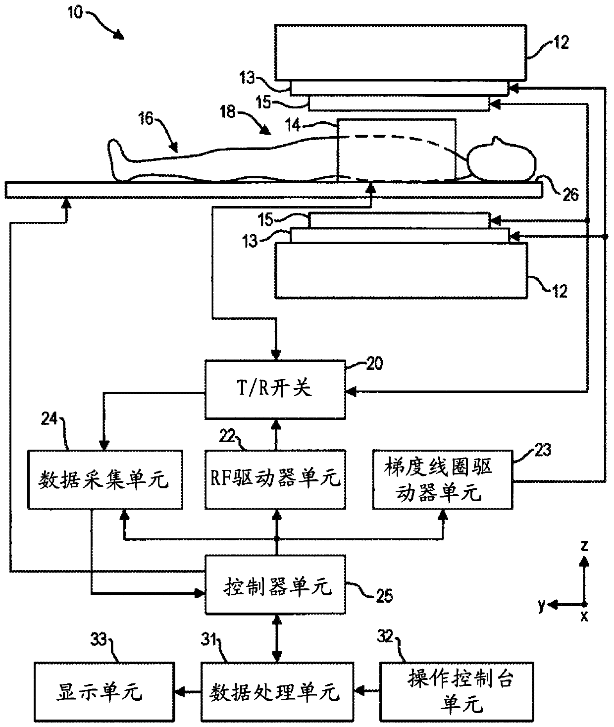
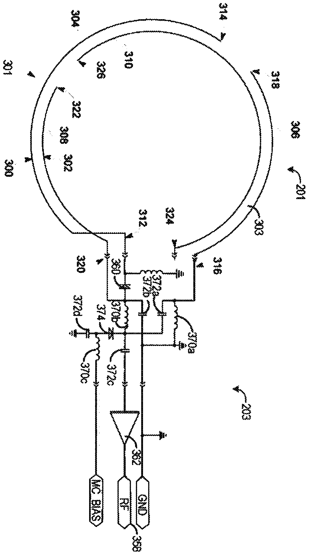
[0020] The following description relates to various embodiments of radio frequency (RF) coils in an MRI system. In particular, systems and methods are provided for low cost, flexible and lightweight RF coils that are effectively transparent in multiple respects. Given the low weight of the coil and the flexible packaging enabled by the RF coil, the RF coil is effectively transparent to the patient. The RF coil is also effectively transparent to other RF coils in the RF coil array due to the minimization of the magnetic and electrical coupling mechanisms. Furthermore, RF coils are effectively transparent to other structures through capacitance minimization and to positrons through mass reduction, enabling the use of RF coils in hybrid positron emission tomography (PET) / MR imaging systems . The RF coils of the present disclosure can be used in MRI systems of various magnetic field strengths.

[0021] The RF coil of the present disclosure includes significantly smaller amounts...


PUM


Abstract

Various methods and systems are provided for a flexible, lightweight, low-cost radio frequency (RF) coil array of a magnetic resonance imaging (MRI) system. In one example, a RF coil array for a MRI system includes a plurality of RF coils, each RF coil comprising an integrated capacitor coil loop; a plurality of coupling electronics units each coupled to a respective coil loop; and a plurality ofwires coupling each coupling electronics unit to an interface board configured to couple to a cable of the MRI system. The RF coil array is a high density (referring to the number of coil elements) anterior array (HDAA) or a high definition (referring to image resolution) anterior array.

Description

[0001] Cross References to Related Applications [0002] This application claims priority to U.S. Provisional Patent Application No. 62 / 426,028, filed November 23, 2016, which is hereby incorporated by reference in its entirety. Background technique [0003] Embodiments of the subject matter disclosed herein relate to magnetic resonance imaging (MRI), and more particularly, to MRI radio frequency (RF) coils. [0004] Magnetic resonance imaging (MRI) is a medical imaging modality that creates images of the inside of the human body without the use of x-rays or other ionizing radiation. MRI systems include superconducting magnets to generate a strong, uniform static magnetic field. When a human body or part of a human body is placed in this magnetic field, the nuclear spins associated with the hydrogen nuclei in the tissue water become polarized, with the magnetic moments associated with these spins preferentially aligned along the direction of the magnetic field, causing a Sma...

Claims


Application Information

Patent Timeline
Patent Type & Authority Applications(China)
IPC IPC(8): A61B5/055G01R33/28
CPCA61B5/055G01R33/3415G01R33/3621G01R33/34007G01R33/28G01R33/3628G01R33/3685
Inventor 纳比勒·马利克迈克尔·克拉克科尔曼·尤哈斯爱德温·艾根布罗特罗伯特·斯托蒙特斯科特·琳赛
Owner GENERAL ELECTRIC CO
Learn More