
A copper pipe crimping device and crimping process for large-scale products

A crimping device and product technology, applied in metal processing, manufacturing tools, metal processing equipment and other directions, can solve the problems of greater impact on production efficiency, inconvenient handling process, low production efficiency, etc., to improve production efficiency, easy assembly, The effect of improving the yield

Active Publication Date: 2021-08-24
SUZHOU JOYO METAL TECH CO LTD
View PDF7 Cites 0 Cited by
  • Summary
  • Abstract
  • Description
  • Claims
  • Application Information

AI Technical Summary

Problems solved by technology

The above-mentioned process needs to be completed after the crimping of the product before the next product can be installed on the machine. The production efficiency is low, especially when assembling large-scale products, due to the large volume, the handling process is inconvenient, which has an impact on production efficiency. bigger

Method used


Image

  • A copper pipe crimping device and crimping process for large-scale products
  • A copper pipe crimping device and crimping process for large-scale products
  • A copper pipe crimping device and crimping process for large-scale products

Examples


Embodiment 1

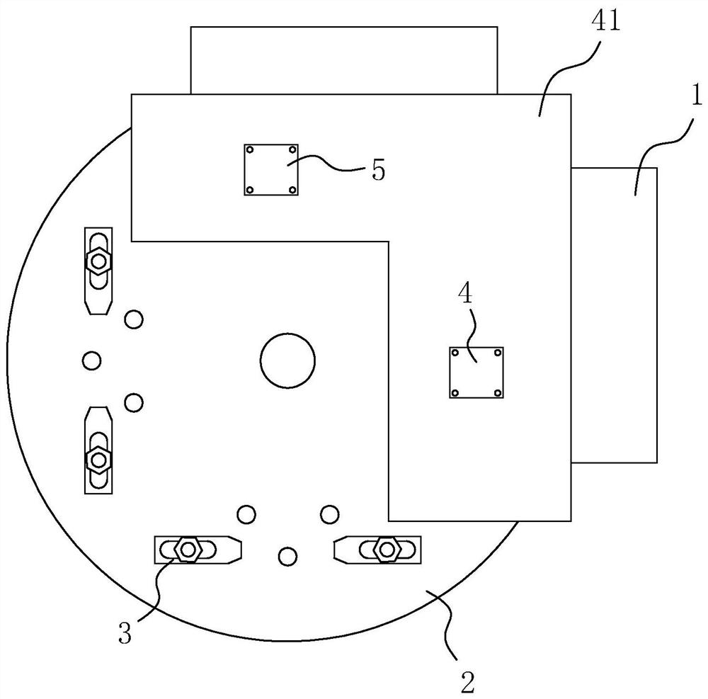
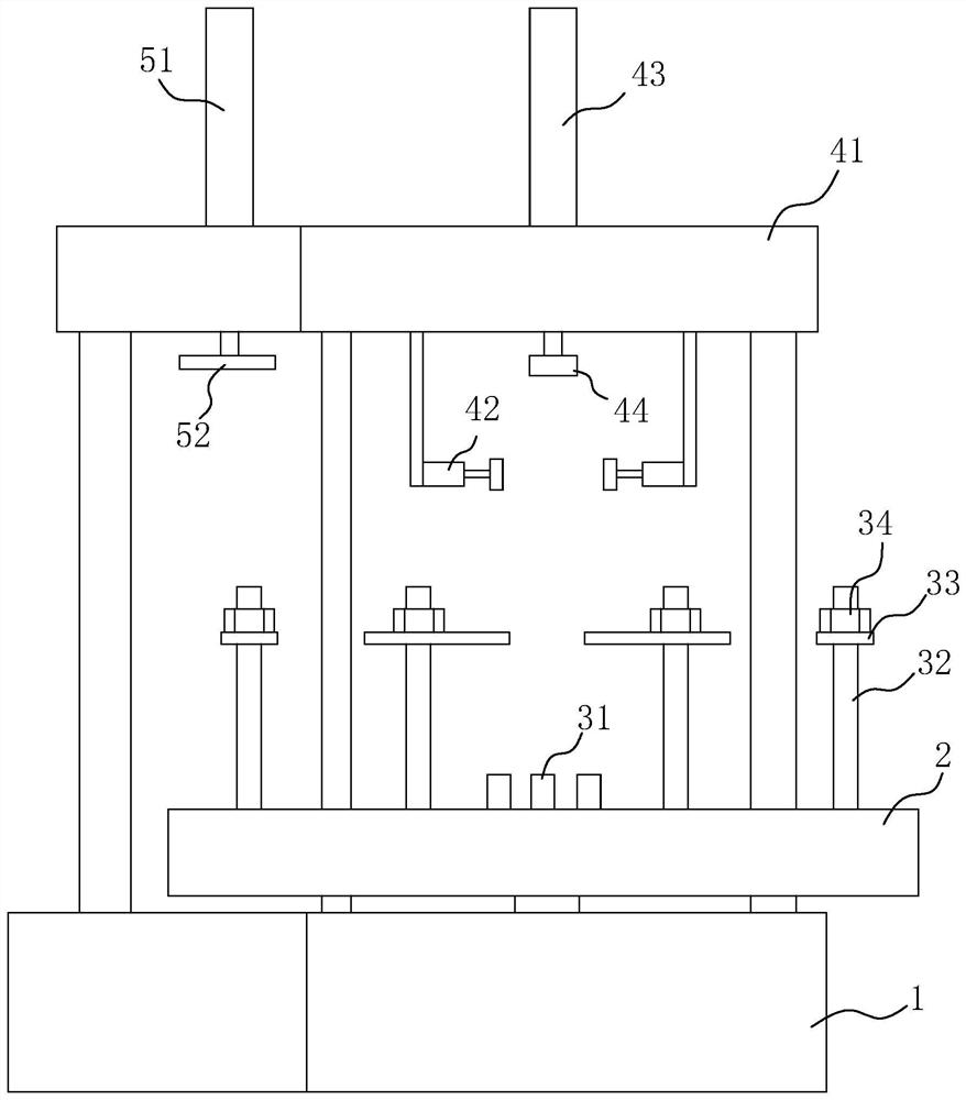
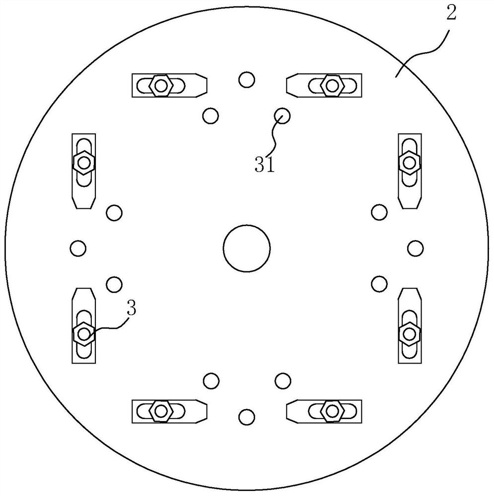
[0040] A large product copper tube crimping device such as figure 1 As shown, it includes: a machine platform 1; a supporting turntable 2 that is rotatably connected to the machine platform 1, a drive motor for driving the supporting turntable 2 to rotate is provided on the machine platform 1, and at least three assemblers are arranged on the supporting turntable 2. position, and each assembly station is equipped with a fixing mechanism 3 for fixing the product to be crimped; carried on the machine 1 for assembling the copper tube to be crimped and pre-pressing the copper tube to be crimped on the product to be crimped a pre-installation mechanism; and a pressing mechanism 5 carried on the press table 41 for press-fitting the copper tube to be crimped into the product to be crimped.

[0041] Specifically, such as figure 2 and image 3As shown, the driving motor (not shown in the figure) is fixed in the machine platform 1 by bolts, and the driving motor is a servo motor, the...

Embodiment 2

[0048] Based on the crimping device of Embodiment 1, this embodiment provides a copper tube crimping process for large-scale products, including:

[0049] Step 1: The product to be crimped is pre-installed on the support turntable 2 through the fixing mechanism 3, the copper tube to be crimped is clamped and fixed under the first hydraulic cylinder 43 by the clamping assembly 42, and the upper end of the copper tube to be crimped The clip is embedded in the pressing sleeve 44, so that the copper pipe to be crimped is in a vertical state, and the clamping assembly 42 will be clamped by it.

[0050] Step 2: The supporting turntable 2 is driven to rotate by driving the motor, and the product to be crimped is moved directly under the pre-installation mechanism.

[0051] Step 3: The first hydraulic cylinder 43 drives the copper tube to be crimped to press down to pre-press and fix the copper tube to be crimped on the product to be crimped. The depth of the crimped copper tube is ge...


PUM


Abstract

The invention relates to a copper tube crimping device and crimping process for large-scale products, wherein the crimping device includes: a machine; a supporting turntable that is rotatably connected to the machine; The driving motor that supports the rotation of the turntable, the support turntable is provided with at least three assembly stations; the pre-installation mechanism carried on the machine table, the pre-installation mechanism includes: a pressing table, a clamping assembly, and a The press table is used to drive the copper tube to press down and pre-press the first hydraulic cylinder fixed on the product to be crimped; and, the press-fit mechanism. Since at least three assembly stations are set up, the product assembly can be carried out at the same time as the press assembly, without the need to disassemble the product after the press assembly is completed and then assemble the product to be crimped, which improves the production efficiency. Two steps of pressing and pressing are used to assemble the copper tube, which makes the copper tube assembly more convenient, has higher precision, and improves the yield.

Description

technical field [0001] The invention relates to the technical field of copper tube assembly equipment, in particular to a copper tube crimping device and a crimping process for large-scale products. Background technique [0002] Assembling copper pipe fittings in products is one of the common processes in the processing of many equipment products. Usually, the copper pipe assembly process is: first assemble the copper pipe on the pressure head of the hydraulic press, and then clamp the product in place On the machine table, align the assembly hole on the product with the copper pipe, and then drive the copper pipe to press down through the hydraulic press, so that the copper pipe and the product can be crimped and assembled together. The above-mentioned process needs to be completed after the crimping of the product before the next product can be installed on the machine. The production efficiency is low, especially when assembling large-scale products, due to the large volu...

Claims


Application Information

Patent Timeline
Patent Type & Authority Patents(China)
IPC IPC(8): B23P19/02B23P19/00
CPCB23P19/00B23P19/001B23P19/02
Inventor 宋晓闪
Owner SUZHOU JOYO METAL TECH CO LTD
Learn More