rear control arm structure

A control arm and structure technology, which is applied to the cantilever mounted on the pivot, vehicle parts, transportation and packaging, etc., can solve the problem of increased stamping, welding and other manufacturing processes, weak strength and rigidity of the rear control arm, and difficult reinforcement plate technology Forming and other issues, to achieve the effect of easy processing and manufacturing, lightweight design, improved structural strength, and good use effect

Active Publication Date: 2020-08-18
GREAT WALL MOTOR CO LTD
View PDF11 Cites 0 Cited by
  • Summary
  • Abstract
  • Description
  • Claims
  • Application Information

AI Technical Summary

Problems solved by technology

In this structure, the reinforcing plate process is not easy to form, and the reinforcing plate and the control arm body are overlapped and welded, and the overall strength and rigidity of the rear control arm are weak; at the same time, the reinforcing plate has no effect on the coil spring seat installed at the bottom of the control arm body. Limit function, there is a risk of the helical spring seat moving when the vehicle is in high-intensity movement
[0004] The second type is the lap joint welding between the main body of the rear control arm, the middle plate and the sealing plate. In the plate, although the movement of the coil spring seat can be restricted, by adding the middle plate, the manufacturing processes such as stamping and welding are increased, which not only increases the production cost, but also greatly increases the overall weight

Method used


Image

  • rear control arm structure
  • rear control arm structure

Examples


Embodiment Construction

[0033] It should be noted that, in the case of no conflict, the embodiments of the present invention and the features in the embodiments can be combined with each other.

[0034] The present invention will be described in detail below with reference to the accompanying drawings and examples.

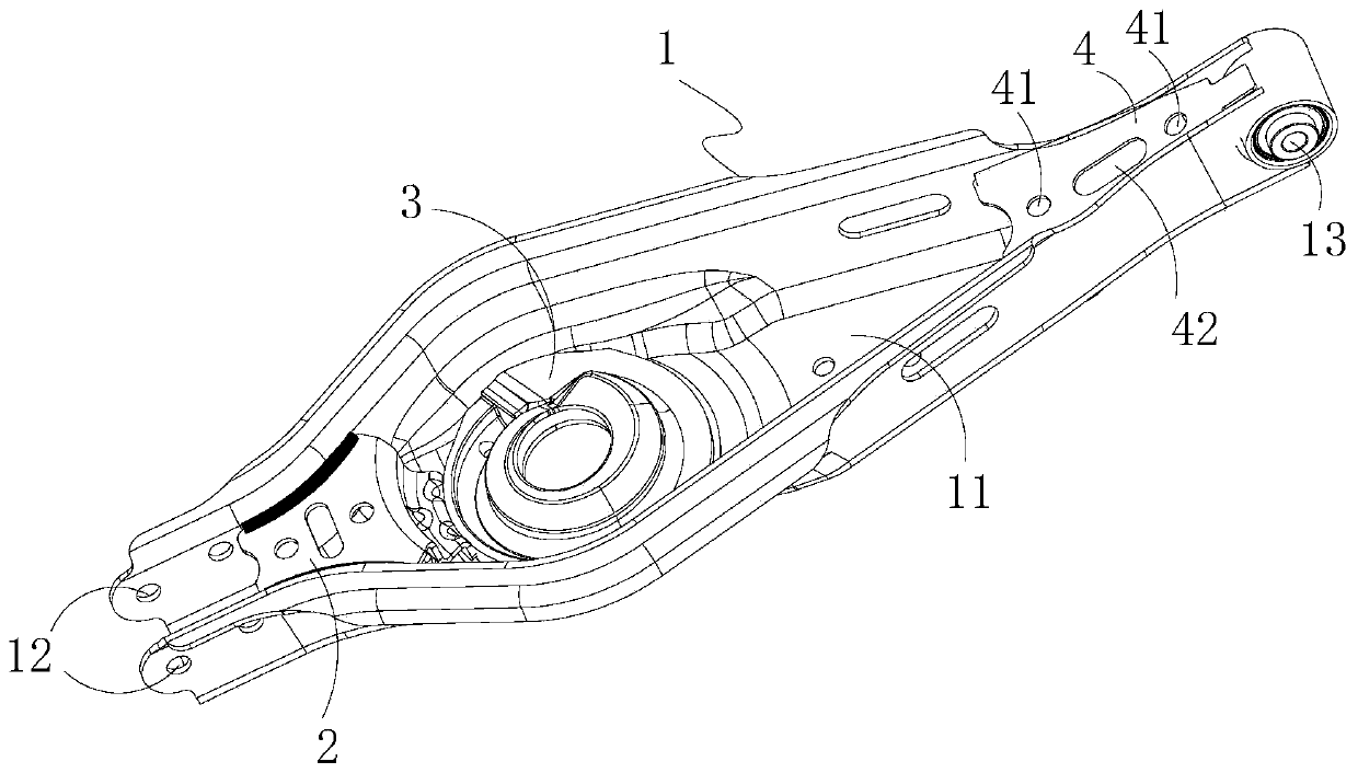
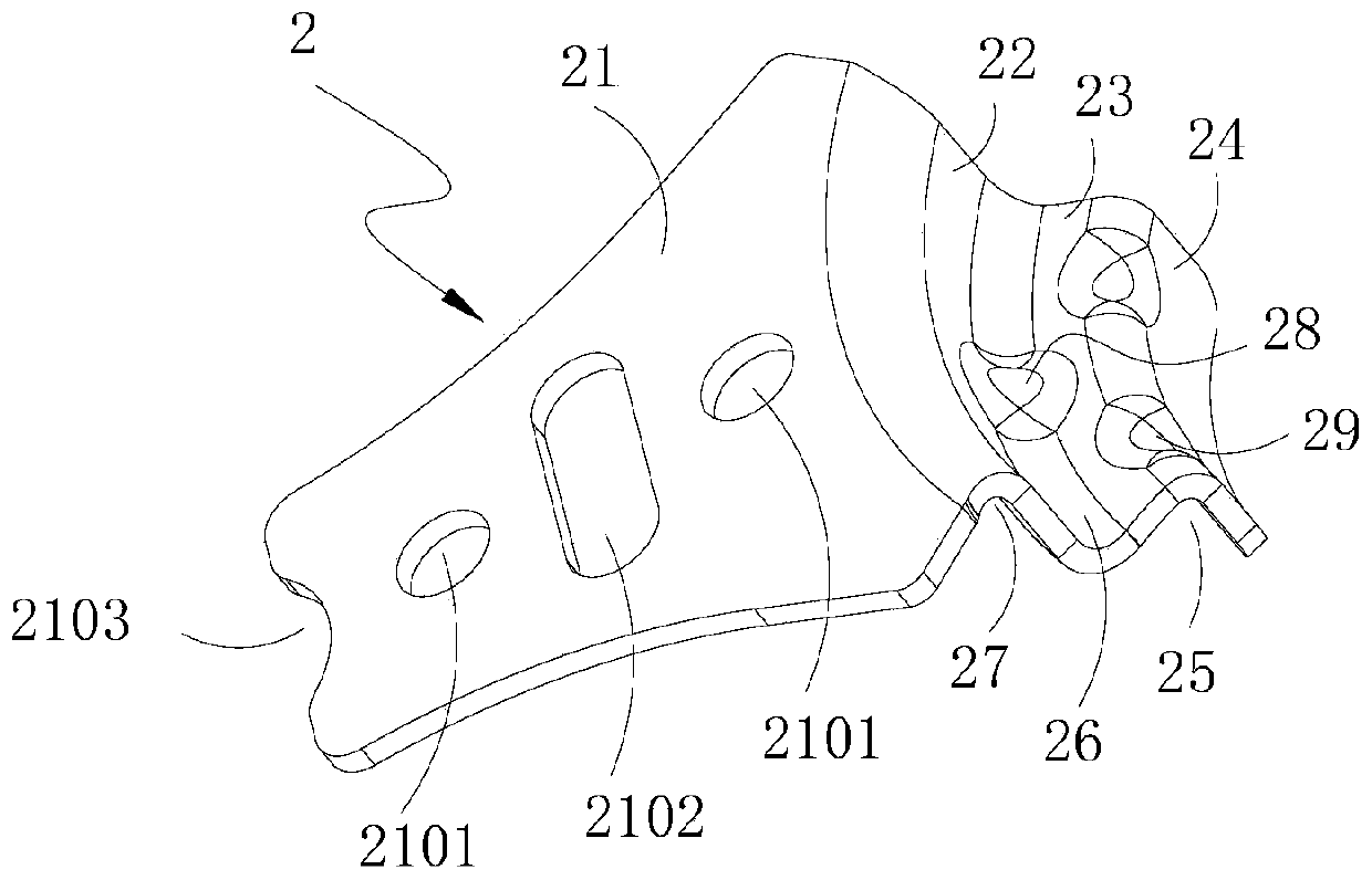
[0035] The invention relates to a structure of a rear control arm, which includes a control arm main body and a first reinforcement part, wherein, an accommodating cavity arranged along the length direction of the control arm main body is formed on the control arm main body, and a bottom of the accommodating cavity is configured for The installation part of the coil spring seat is installed; the first reinforcement part is accommodated in the accommodating cavity and is located on one side of the installation part, and the first reinforcement part is fixedly connected between the two side walls of the accommodating cavity to The side wall constitutes a rigidly supported reinforcing unit,...


PUM


Abstract

The invention relates to a structure of a rear control arm, which includes a control arm main body and a first reinforcement part, wherein, an accommodating cavity arranged along the length direction of the control arm main body is formed on the control arm main body, and a bottom of the accommodating cavity is configured for The installation part of the coil spring seat is installed; the first reinforcement part is accommodated in the accommodating cavity and is located on one side of the installation part, and the first reinforcement part has a reinforcement unit fixedly connected between the two side walls of the accommodating cavity, And the limiting unit integrally connected with the reinforcement unit can be configured to abut against one side of the coil spring seat installed at the installation part to form a limit to the radial movement of the coil spring seat. In the present invention, by setting the first reinforcement part, not only the reinforcement unit can form a rigid support for the two side walls of the control arm body, but also the rear control arm structure has higher strength and rigidity; the limit unit can also eliminate the high-intensity movement of the whole vehicle. The risk of the helical spring seat moving inside the main body of the control arm, and the structure of the rear control arm is simple, which can facilitate lightweight design.

Description

technical field [0001] The invention relates to the technical field of auto parts, in particular to a rear control arm structure. Background technique [0002] The suspension control arm is used to connect the steering knuckle and the subframe, and its structural strength determines the performance of the suspension system. In the prior art, the suspension rear control arm mainly has two structural forms: [0003] The first type is lap welding between the main body of the control arm and the reinforcement plate, that is, the two ends of the reinforcement plate are overlapped and welded on the top surface of the main body of the control arm. In this structure, the reinforcing plate process is not easy to form, and the reinforcing plate and the control arm body are overlapped and welded, and the overall strength and rigidity of the rear control arm are weak; at the same time, the reinforcing plate has no effect on the coil spring seat installed at the bottom of the control arm...

Claims


Application Information

Patent Timeline
Patent Type & Authority Patents(China)
IPC IPC(8): B60G7/00
CPCB60G7/001
Inventor 冯世东马晶晶王志超刘志松闫勇王宁武刘峻洁刘春淼夏超赵晓坤于巨滨王亚洲柏华杰宋操
Owner GREAT WALL MOTOR CO LTD
Why Eureka
Try Eureka