Air cooler and method for enabling air cooler to drain no water

A cooling fan and fan technology, applied in the direction of preventing condensed water, heating methods, noise suppression, etc., can solve problems such as drainage troubles, and achieve the effect of low noise

Pending Publication Date: 2019-07-05
杭州医维之星医疗技术有限公司
View PDF0 Cites 2 Cited by
  • Summary
  • Abstract
  • Description
  • Claims
  • Application Information

AI Technical Summary

Problems solved by technology

[0004] The purpose of this application is to provide a cooling fan to solve the technical problem of troublesome drainage in the prior art

Method used


Image

  • Air cooler and method for enabling air cooler to drain no water
  • Air cooler and method for enabling air cooler to drain no water
  • Air cooler and method for enabling air cooler to drain no water

Examples


Embodiment 1

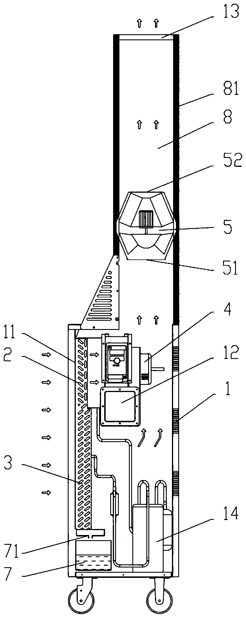
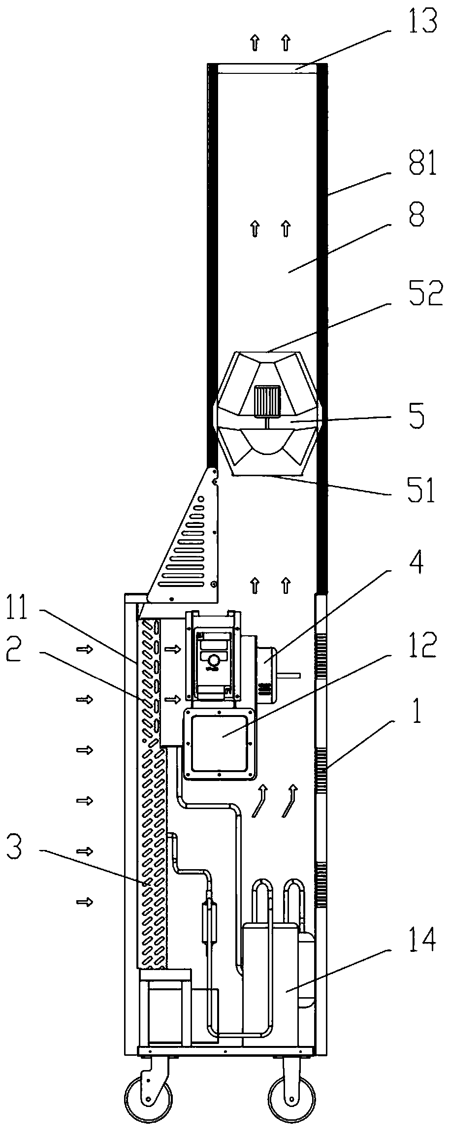
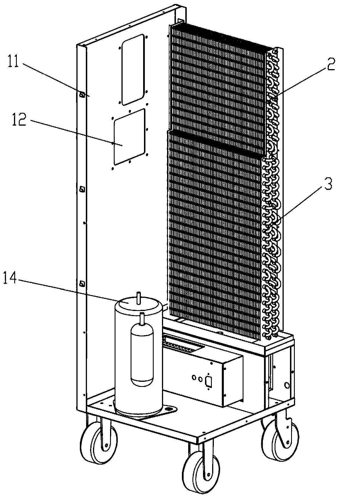
[0038] See figure 1 , figure 2 , image 3 , Figure 4 , Figure 5 , Figure 6 , Figure 7 , a cold air blower 100, comprising a casing 1, the casing 1 is provided with an air inlet 11, a cold air outlet 12 and a hot air outlet 13, and the casing 1 includes a compressor 14, an evaporator 2, a condenser 3, a hot air Fan 5 and air-cooling fan 4, evaporator 2 includes evaporation straight pipes and cooling fins arranged vertically to each other, condenser 3 includes condensing straight pipes 31 and cooling fins arranged vertically to each other, and evaporator 2 is arranged above the condenser 3 , and the cooling fins and heat dissipation fins are arranged vertically, and are arranged at intervals up and down. The surface of the heat dissipation fins is provided with a hydrophilic layer. Located on the side wall of the casing 1, the hot air outlet 13 is arranged on the top of the casing 1, a hot air pipeline 8 is arranged below the hot air outlet 13, and a hot air blower 5 ...

specific Embodiment approach

[0070] 1. Increasing the number of rows of straight condensing pipes in the first direction is equivalent to extending the length of the condenser, that is, the distance between two adjacent straight condensing pipes along the first direction remains unchanged, and increasing the straight condensing pipes along the first The number of settings for the direction.

[0071] 2. Reduce the arrangement spacing of the straight tube array of the condenser and increase the distribution density of the straight tubes. That is, the distance between two adjacent straight condensation pipes along the first direction or the second direction is reduced.

[0072] 3. Increase the number of condensing straight pipe columns.

[0073] Therefore, in a specific implementation of the present embodiment, compared with the prior art, some parameters of the condenser are significantly different: the row spacing of the condensing straight pipes in the condenser is reduced from 21 mm to 18 mm, which is r...

Embodiment 2

[0083] See figure 1 , figure 2 , including the air cooler 100 of Embodiment 1 of the above-mentioned air cooler, the axis of the air inlet 11 and the axis of the hot air outlet 13 are vertically arranged, the air inlet 11 and the hot air outlet 13 are respectively located on both sides of the condenser 3, and the hot air outlet The tuyere 13 is located above the air inlet 11 .

[0084] The axis of the air inlet is set perpendicular to the axis of the hot air outlet. The air inlet and the hot air outlet are respectively located on both sides of the condenser, and the hot air outlet is located above the air inlet. The hot air fan will transport the gas absorbed from the air inlet to the When the hot air is out of the air, it needs to turn and rise.

[0085] See figure 1 , figure 2 The hot air fan 5 is provided with an air inlet 51 and an air outlet 52, the axis of the air inlet 51 is arranged coaxially with the axis of the air outlet 52, and the axis of the air outlet 52 i...


PUM


Abstract

The invention relates to an air cooler and a method for enabling the air cooler to drain no water, relates to the technical field of refrigerating equipment, and solves the technical problem of troublesome drainage in the prior art. The air cooler comprises a shell; the shell is provided with an air inlet, a cold air outlet and a hot air outlet; the shell comprises an evaporator, a condenser, a hot air fan and a cold air fan; the evaporator comprises an evaporation straight pipe and a cold conducting fin; the condenser comprises a condensation straight pipe and a cooling fin; the evaporator isarranged above the condenser; the cold conducting fin and the cooling fin are arranged at intervals up and down; the air inlet is formed in the side wall of the shell; the cold air outlet is formed in the side wall of the shell; the hot air outlet is formed in the top of the shell; a hot air pipe is arranged under the hot air outlet; the hot air fan is mounted in the hot air pipe; and the hot airfan is a mixed-flow fan. The air cooler has no need to drain water, facilitates recycling of water resources, improves environmental protection, and promotes the harmonious development of human and nature.

Description

technical field [0001] The present application relates to the technical field of refrigeration equipment, in particular to a cooling fan and a method for making the cooling fan unnecessary to drain. Background technique [0002] Some indoor high-power electrical equipment, such as large-scale computers, medical CT machines, etc., will generate a lot of heat during high-load operation, and relying on their own fan cooling system is still insufficient, and an additional cooling fan is needed to blow cold air through the pipeline to further improve the equipment. Excellent heat dissipation efficiency to meet the stability of high-load operation of the equipment. [0003] Existing refrigeration equipment often adopts air coolers, but the air coolers in the prior art will generate more condensed water during work, and drainage is often troublesome. For example, the following measures are often used for drainage: one is to collect water through a water tank, and when the water is...

Claims


Application Information

Patent Timeline
Patent Type & Authority Applications(China)
IPC IPC(8): F24F5/00F24F13/22F24F13/24F24F13/30
CPCF24F5/0035F24F13/222F24F13/24F24F13/30F24F2013/242
Inventor 杨华
Owner 杭州医维之星医疗技术有限公司
Why Eureka
Try Eureka