Projectile-fuse connection structure and initiation device
A connection structure and fuze technology, applied in fuzes, weapon accessories, offensive equipment, etc., can solve the problems of weak stress wave attenuation and filtering, high rigidity of the threaded connection structure, and damage to the fuze, saving assembly and disassembly time, avoiding Fuze damage, the effect of avoiding damage
- Summary
- Abstract
- Description
- Claims
- Application Information
AI Technical Summary
Problems solved by technology
Method used
Image
Examples
Embodiment 1
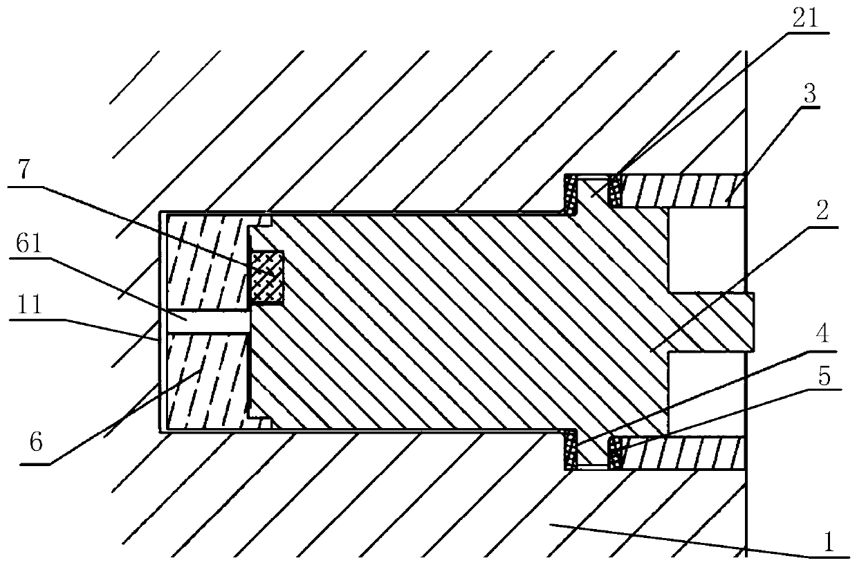
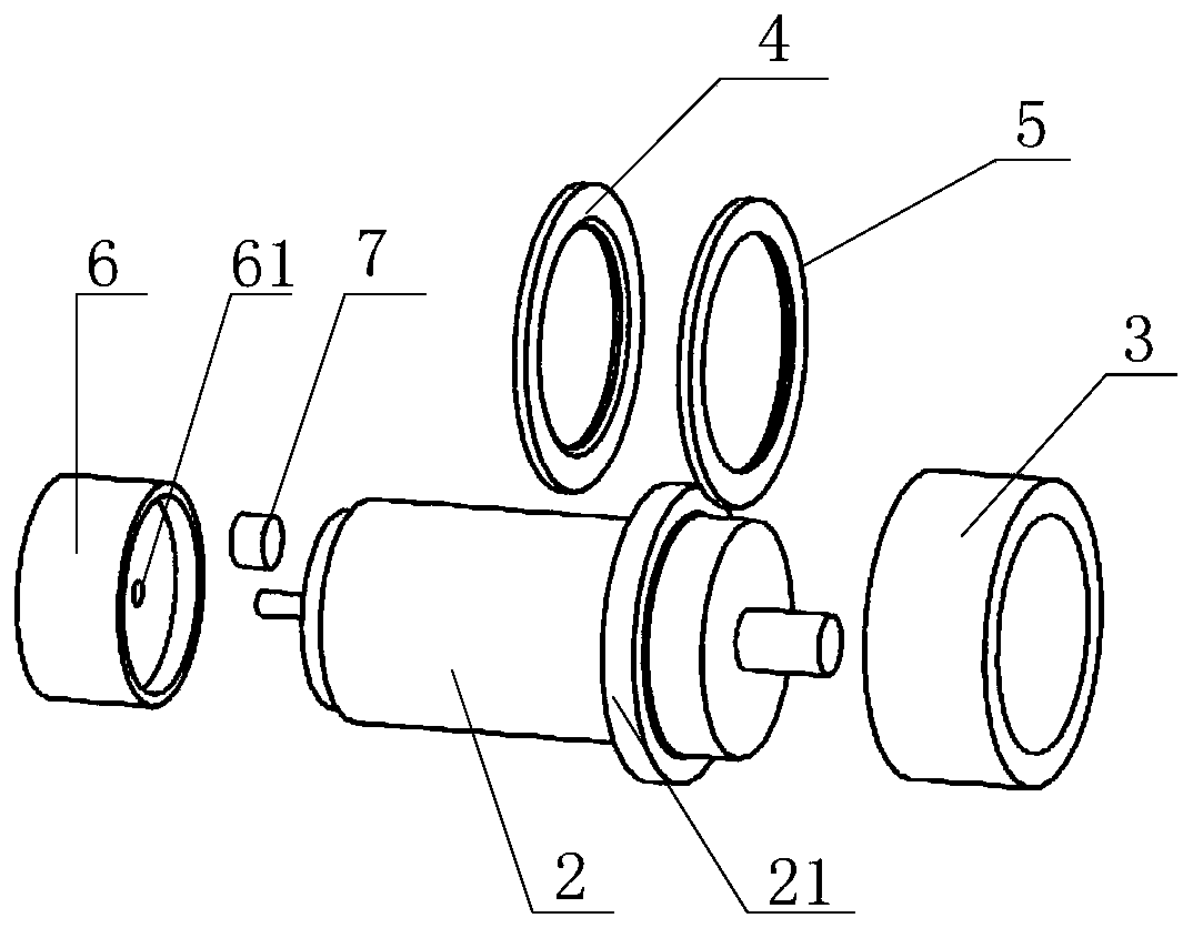
[0032] This embodiment provides a pop-up connection structure, please refer to figure 1 , figure 2 and image 3 , the elastic connection structure includes a projectile body 1, a fuze 2 and a fuze pressure ring 3; a mounting hole 11 is opened on the projectile body 1, and the fuze pressure ring 3 is configured to crimp the fuze 2 inside the installation hole 11 and make the fuze A gap is formed between the peripheral wall of 2 and the peripheral wall of the mounting hole 11. Specifically, the installation hole 11 can be opened on the tail section of the missile body 1 .
[0033] In this embodiment, the fuze 2 is crimped on the projectile body 1 with the fuze pressure ring 3, and only needs to take off the fuze pressure ring 3 during disassembly. Compared with the fuze 2 and the projectile body 1 in the prior art The multi-turn thread connection between them has the beneficial effect of simple disassembly and can save assembly and disassembly time;
[0034] And, in this em...
Embodiment 2
[0047] This embodiment provides a detonating device, the detonating device includes the spring connection structure provided in the first embodiment.
[0048] see figure 1 , figure 2 and image 3 , the elastic connection structure includes a projectile body 1, a fuze 2 and a fuze pressure ring 3; a mounting hole 11 is opened on the projectile body 1, and the fuze pressure ring 3 is configured to crimp the fuze 2 inside the installation hole 11 and make the fuze A gap is formed between the peripheral wall of 2 and the peripheral wall of the mounting hole 11. Specifically, the installation hole 11 can be opened on the tail section of the missile body 1 .
[0049] In this embodiment, the fuze 2 is crimped on the projectile body 1 with the fuze pressure ring 3, and only needs to take off the fuze pressure ring 3 during disassembly. Compared with the fuze 2 and the projectile body 1 in the prior art The multi-turn thread connection between them has the beneficial effect of sim...
PUM
 Abstract
Description
Claims
Application Information
 - R&D
- Intellectual Property
- Life Sciences
- Materials
- Tech Scout
- Unparalleled Data Quality
- Higher Quality Content
- 60% Fewer Hallucinations
Browse by: Latest US Patents, China's latest patents, Technical Efficacy Thesaurus, Application Domain, Technology Topic, Popular Technical Reports.
© 2025 PatSnap. All rights reserved.Legal|Privacy policy|Modern Slavery Act Transparency Statement|Sitemap|About US| Contact US: help@patsnap.com


