Circular grating sensor angle measurement error correcting method based on error source analysis

An error correction, circular grating technology, applied in the field of measuring instruments, can solve the problems of lack of in-depth research on specific gravity, inability to guide the installation of precision shafting and adjustment of grating discs, and inability to analyze various errors in the design and assembly of rotating joints.

Active Publication Date: 2019-07-05
HEFEI UNIV OF TECH
View PDF4 Cites 12 Cited by
  • Summary
  • Abstract
  • Description
  • Claims
  • Application Information

AI Technical Summary

Problems solved by technology

Commonly used methods include the single-reading head correction method, using an autocollimator, polygonal prism or temporarily installing a higher-precision circular grating sensor to obtain discrete calibration data, and then using algorithms such as least squares algorithm, particle swarm algorithm, and neural network algorithm Fitting the discrete data obtained by calibration without in-depth study of the proportion of each error item, so it is impossible to guide the installation and adjustment of the precision shaft system and the installation of the grating disk in the rotary joint of this type of instrument
The commonly used multi-reading head self-calibration method is also unable to analyze various errors and guide the design and assembly of the rotary joint, and the cost increases significantly due to the use of multiple reading heads
The angle measurement error correction method of the circular grating sensor commonly used now uses the "black box method", without in-depth analysis of the main error sources causing the angle measurement error, and the proportion of each error item cannot be obtained; and it needs to be completely installed on the rotating shaft After the completion, the error detection can be performed by fixing the prism with the fixture

Method used


Image

  • Circular grating sensor angle measurement error correcting method based on error source analysis
  • Circular grating sensor angle measurement error correcting method based on error source analysis
  • Circular grating sensor angle measurement error correcting method based on error source analysis

Examples


Embodiment Construction

[0039] The technical solutions in the embodiments of the present invention will be clearly and completely described below in conjunction with the accompanying drawings.

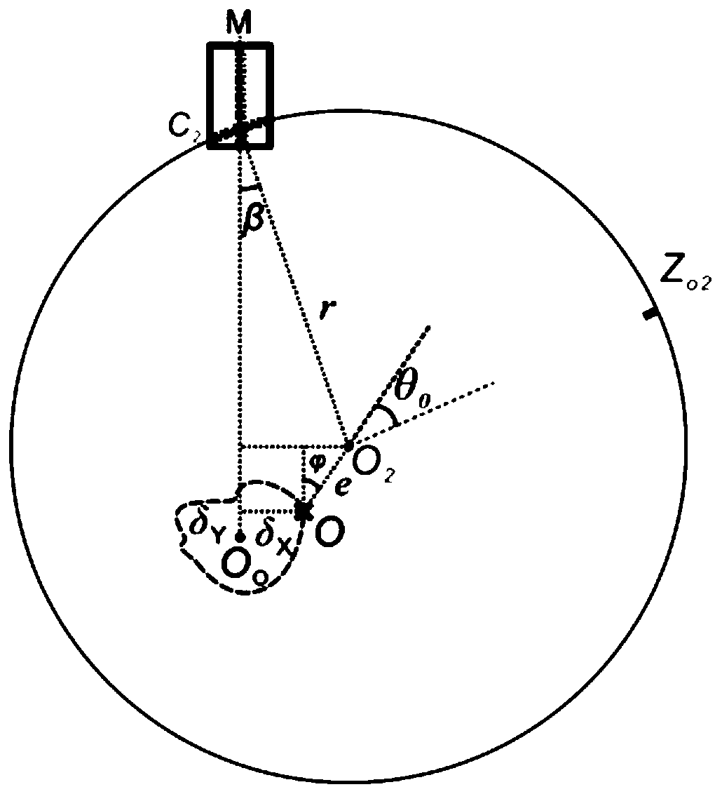
[0040] The angle measurement error correction method of the circular grating sensor based on the error source analysis of the present invention does not need to use the clamping device to install the multi-faceted prism and the autocollimator, but detects the main error items during the assembly and adjustment process of the precision shaft system , including detecting the amount of radial error movement during the installation and adjustment of the rotating shaft, and detecting the installation eccentricity of the grating disc relative to the rotating shaft during the installation of the grating disc, and bringing it into the angle measurement error model of the circular grating sensor to obtain the angle measurement error. Compared with the method of obtaining the angle measurement error by fixing the polyh...


PUM


Abstract

The invention belongs to the field of measuring instruments, and discloses a circular grating sensor angle measurement error correcting method based on error source analysis. The circular grating sensor angle measurement error correcting method comprises the steps of: establishing an angle measurement error model of a circular grating sensor; taking an image picture of surface grooves of a gratingdisc of the circular grating sensor by means of a CCD camera and a microscope of an eccentricity detecting device; adopting an image processing method on right side end point coordinates of each grooves of each image to obtain an installation grating disc eccentric magnitude e and an installation eccentric angle theta 0; detecting a radial error delta Y(theta) of a rotating shaft at the end surface of the grating disc; substituting the measured e, theta 0 and the delta Y(theta) into the angle measurement error model to obtain an angle measurement error Delta theta of the circular grating sensor, wherein a correction function is -Delta theta. The circular grating sensor angle measurement error correcting method can perform online adjustment on the rotating shaft and the grating disc conveniently, improve the angle measurement precision of the circular grating sensor and reduce errors.

Description

technical field [0001] The invention belongs to the field of measuring instruments, in particular to a method for correcting an angle measurement error of a circular grating sensor based on error source analysis. Background technique [0002] The joint coordinate measuring machine is an important 3D macroscopic precision measuring instrument in the modern manufacturing industry. The measurement accuracy of this type of instrument is significantly affected by the angle measurement accuracy of the circular grating sensor installed in the rotating joint. Factors that affect the angular measurement accuracy of the circular grating sensor include the installation of the grating disk, the radial error movement of the rotating shaft, the error of the grating disk marking line, and the temperature. Among them, the installation eccentricity of the grating disc of the circular grating sensor and the radial error motion of the rotating shaft are the most important factors that cause th...

Claims


Application Information

Patent Timeline
Patent Type & Authority Applications(China)
IPC IPC(8): G01B11/26
CPCG01B11/26
Inventor 于连栋贾华坤姜一舟赵会宁夏豪杰李维诗
Owner HEFEI UNIV OF TECH
Why Eureka
Try Eureka