Detecting device for deformation joint leakage of circular tunnels

A detection device and deformation joint technology are applied in the field of tunnel leakage detection, which can solve the problems of leakage at joints, hidden dangers, and unfavorable long-term safe operation of tunnels, so as to improve detection efficiency, avoid loss of human and material resources, and improve detection efficiency. The result is obvious and intuitive

Pending Publication Date: 2019-07-05
美肯沃利工程技术咨询(北京)有限公司
View PDF0 Cites 2 Cited by
  • Summary
  • Abstract
  • Description
  • Claims
  • Application Information

AI Technical Summary

Problems solved by technology

[0003] In actual engineering, hydraulic tunnels generally have a section length of 6-12m. When laying water-stop sheets at the junction of two tunnel sections, it is necessary to detect whether the water-stop sheets are damaged. However, in the prior art, there is no effective detection method Inspection can only be carried out by manual regular inspection. If leakage occurs, it is difficult to detect which joint is leaking. There are hidden dangers, which is not conducive to the long-term safe operation of the tunnel.

Method used


Image

  • Detecting device for deformation joint leakage of circular tunnels
  • Detecting device for deformation joint leakage of circular tunnels
  • Detecting device for deformation joint leakage of circular tunnels

Examples


Embodiment 1

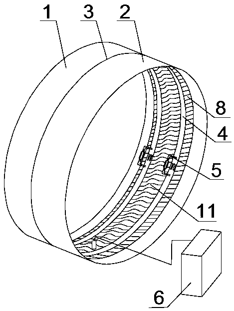
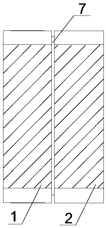
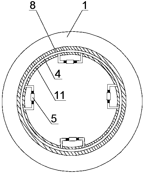
[0028] Such as figure 1 As shown, a detection device for the leakage of circular tunnel deformation joints, the device is detachably installed at the expansion joint 3 between the front circular tunnel 1 and the rear circular tunnel 2, and the expansion joint 3 is provided with The water stop sheet 7 tightly combined with the circular tunnels on both sides, such as figure 2 As shown, the water stop sheet 7 is located in the middle part of the expansion joint 3, and both left and right are embedded in the concrete lining the tunnel. The detection device includes an annular rubber belt 8, an air pressure detection device 6 and two sets of ring-shaped toothed connection steel plates 4, wherein, The outer diameter of the annular rubber belt 8 is consistent with the inner diameter of the circular tunnel, the outer diameter of the toothed connecting steel plate 4 is consistent with the inner diameter of the annular rubber belt 8, the annular rubber belt 8 is attached to the inner w...

Embodiment 2

[0030] The annular rubber belt 8 is provided with a hollow rubber hemisphere 9 that protrudes toward the center of the tunnel. The rubber hemisphere 9 and the annular rubber belt 8 form an integral structure, and the interior communicates with the closed space, and is located between two sets of toothed connecting steel plates 4. The top of the hemisphere 9 is provided with an inflation valve, and the air pressure detection device 6 is detachably connected to the rubber hemisphere 9 by connecting the inflation valve to the rubber hemisphere 9, so as to detect the air pressure in the confined space.

Embodiment 3

[0032]This embodiment is a further optimization of Embodiment 1: in this embodiment, two parallel annular rubber rings 10 are respectively provided on both sides of the contact surface between the annular rubber belt 8 and the inner wall of the circular tunnel, and the two annular rubber rings 10 on each side A recessed area is formed between the rubber rings 10, and the tightening positions of the two groups of toothed connecting steel plates 4 correspond to the recessed areas respectively, and the annular rubber ring 8 is squeezed by the toothed connecting steel plates 4 to the annular rubber belt 8. 10 is in an open state on both sides and tightly combined with the inner wall of the circular tunnel, which ensures the tightness of the device during detection.

[0033] The method of use of the present invention is as follows: when testing, the annular rubber belt is closely attached to the tunnel, and then the toothed connecting steel plate is used to firmly clamp the annular ...


PUM


Abstract

The invention discloses a detecting device for deformation joint leakage of circular tunnels. The device is detachably arranged at an expansion joint provided with a water stop piece in an embedded manner and located between two circular tunnels, and the detecting device comprises an annular rubber band, an air pressure detecting device and two sets of annular tooth-type connecting steel plates, wherein reverse screw devices are fixed at several joints of each set of tooth-type connecting steel plates, the tooth-type connecting steel plates are pushed by the reverse screw devices to move inthetangential direction at the toothed connecting port such that the tooth-type connecting steel plates can tightly support the annular rubber band onto the inner sides of the circular tunnels, the annular rubber band is provided with an inflation valve, and the air pressure detecting device is connected to the inflation valve through a conduit to detect the air pressure in the sealed space formed by the water stop piece, the expansion joint and the annular rubber band. The detecting device can be used to effectively confirm which section of the expansion joint of the hydraulic tunnels is damaged, and avoid the loss on the human and material resources brought about by large-scale inspection of the hydraulic tunnels.

Description

technical field [0001] The invention relates to the field of tunnel leakage detection, in particular to a detection device for the leakage of circular tunnel deformation joints. Background technique [0002] my country is the country with the most tunnels in the world. In the past, the construction standards were low, and water leakage was common after the tunnels were completed. At present, my country's tunnel construction standards have been greatly improved, and the waterproof and drainage technology has also made great progress, but there is still a considerable gap compared with the international advanced level. Concrete and reinforced concrete linings are poured in sections and blocks. In order to prevent cracks caused by concrete drying shrinkage and temperature stress, circumferential expansion joints are provided between adjacent sections. [0003] In actual engineering, hydraulic tunnels generally have a section length of 6-12m. When laying water-stop sheets at th...

Claims


Application Information

Patent Timeline
Patent Type & Authority Applications(China)
IPC IPC(8): G01M3/26
CPCG01M3/26
Inventor 刘英杰颜廷松
Owner 美肯沃利工程技术咨询(北京)有限公司
Why Eureka
Try Eureka