Transformer temperature controller based on optical fiber temperature measurement

An optical fiber temperature measurement and transformer technology, which is applied to transformer/inductor components, thermometer applications, instruments, etc., can solve the problems of difficult maintenance of sealing system components, reduced measurement accuracy, and long thermal equilibrium time. The effect of high reliability, improved reliability and fast response speed

Pending Publication Date: 2019-07-05
大连世有电力科技有限公司
View PDF0 Cites 3 Cited by
  • Summary
  • Abstract
  • Description
  • Claims
  • Application Information

AI Technical Summary

Problems solved by technology

[0004] The temperature sensing package, sensing conduit and copper body dissipate the heat at the temperature measuring point, resulting in a long time for thermal equilibrium. In addition, it takes a long time for the internal pressure and external pressure of the copper body to reach equilibrium, so the response speed is slow;
[0005] 2. The measurement accuracy is greatly affected by factors such as ambient temperature, atmospheric pressure, capillary transmission distance, and mechanical components, which reduces the measurement accuracy
[0006] 3. The components in the sealing system are difficult to maintain, and once the copper body is damaged, the liquid and gas inside will leak, which will directly lead to the scrapping of the thermostat
[0007] Optical fiber temperature measurement has been used in many fields, consisting of a fiber optic temperature measurement host, a temperature measurement fiber and a fiber optic temperature probe. It has the advantages of simple structure, fast response, high accuracy and reliability. However, due to the structure of the transformer and the use of Due to the particularity of the environment, so far there has been no report on the application of optical fiber temperature measurement to transformer temperature detection

Method used


Image

  • Transformer temperature controller based on optical fiber temperature measurement
  • Transformer temperature controller based on optical fiber temperature measurement

Examples


Embodiment Construction

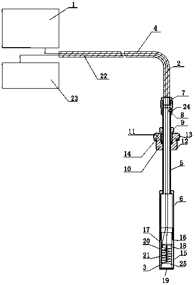
[0012] The transformer oil temperature controller based on optical fiber temperature measurement of the present invention, such as figure 1 Shown: Same as the prior art, there is an optical fiber temperature measuring host 1, the optical fiber temperature measuring host 1 is connected to the optical fiber temperature measuring probe 3 through the temperature measuring optical fiber 2, the difference from the prior art is that the optical fiber temperature measuring host 1 to The optical fiber 2 of the optical fiber temperature measuring probe 3 is sequentially covered with a metal hose 4, an extension tube 5 and an optical fiber protective cover 6. The metal hose 4 is a serpentine tube, and the extension tube 5 can be a stainless steel tube. The ends of the metal hose 4 are fixed. For some fixing parts 7, the end of the long pipe 5 is fixed with a joint 8 through a screw 24, and the fixing part 7 is threadedly connected with the joint 8. For secondary protection, the part of th...


PUM


Abstract

The invention discloses a transformer temperature controller based on optical fiber temperature measurement. The transformer temperature controller is characterized in that: an optical fiber from an optical fiber temperature measurement host to an optical fiber temperature measurement probe is sequentially sleeved with a metal hose, a guiding long pipe and an optical fiber protective cover, wherein the metal hose is connected with the guiding long pipe through a fixing piece and a joint thread; a mounting screw is sleeved on the guiding long pipe, a mounting nut is connected with an external thread of the mounting screw, the lower end of the mounting nut is provided with an external thread used for being connected with a temperature measuring blind pipe of the transformer, the upper end ofthe mounting nut is provided with a circle of boss, and a sealing gasket is fixed below the boss; the lower end of the optical fiber protective cover is connected with a thermal simulation shell in an internally threaded manner, an inner core fixed by a clamp spring is arranged in the thermal simulation shell, the bottom of the thermal simulation shell is provided with a cover bottom, the centerof the inner core is provided with a temperature measuring hole with the built-in optical fiber temperature measurement probe, a heating coil is wound outside the inner core, and the heating coil is connected with a current transformer through a wire arranged in the metal hose, the guiding long pipe and the optical fiber protective cover.

Description

technical field [0001] The invention relates to a transformer temperature controller, in particular to a transformer temperature controller based on optical fiber temperature measurement with fast response speed, high accuracy and reliability. Background technique [0002] The existing transformer temperature controller is equipped with a converter connected to the transformer current transformer (CT). The converter adjusts the output current of the transformer current transformer to meet the temperature difference value of copper oil through internal current transformers and resistors and other components. After the current is connected to the heating element. The heating element is placed in a copper body with an inner cavity, and there is a push rod at the front end of the copper body. The inner cavity of the copper body communicates with the temperature-sensing package through a sensing tube (capillary), and the sealing system composed of the temperature-sensing package,...

Claims


Application Information

Patent Timeline
IPC IPC(8): H01F27/40G01K13/00G01K11/32
CPCH01F27/402G01K11/32G01K13/00H01F2027/406H01F2027/404
Inventor 王世有
Owner 大连世有电力科技有限公司
Why Eureka
Try Eureka