Organic light-emitting diode and preparation method thereof

A light-emitting diode, organic technology, applied in semiconductor/solid-state device manufacturing, electrical components, electric solid-state devices, etc., can solve problems such as reducing the performance of OLED devices

Inactive Publication Date: 2019-07-05
SHANGHAI UNIV
View PDF10 Cites 1 Cited by
  • Summary
  • Abstract
  • Description
  • Claims
  • Application Information

AI Technical Summary

Problems solved by technology

The commonly used hole injection material in the solution method is PEDOT:PSS, which has good conductivity, high transparency and suitable work function, but because PEDOT:PSS is an acidic organic compound and is easy to absorb moisture in the air, the above characteristics will Reduce the performance of OLED devices

Method used


Image

  • Organic light-emitting diode and preparation method thereof
  • Organic light-emitting diode and preparation method thereof
  • Organic light-emitting diode and preparation method thereof

Examples


preparation example Construction

[0040] The present invention also provides a method for preparing the organic light emitting diode, comprising the following steps:

[0041] After the PEDOT:PSS solution is spin-coated on the surface of the ITO substrate, the first annealing is carried out to obtain the PEDOT:PSS layer; the solvent of the PEDOT:PSS solution is water;

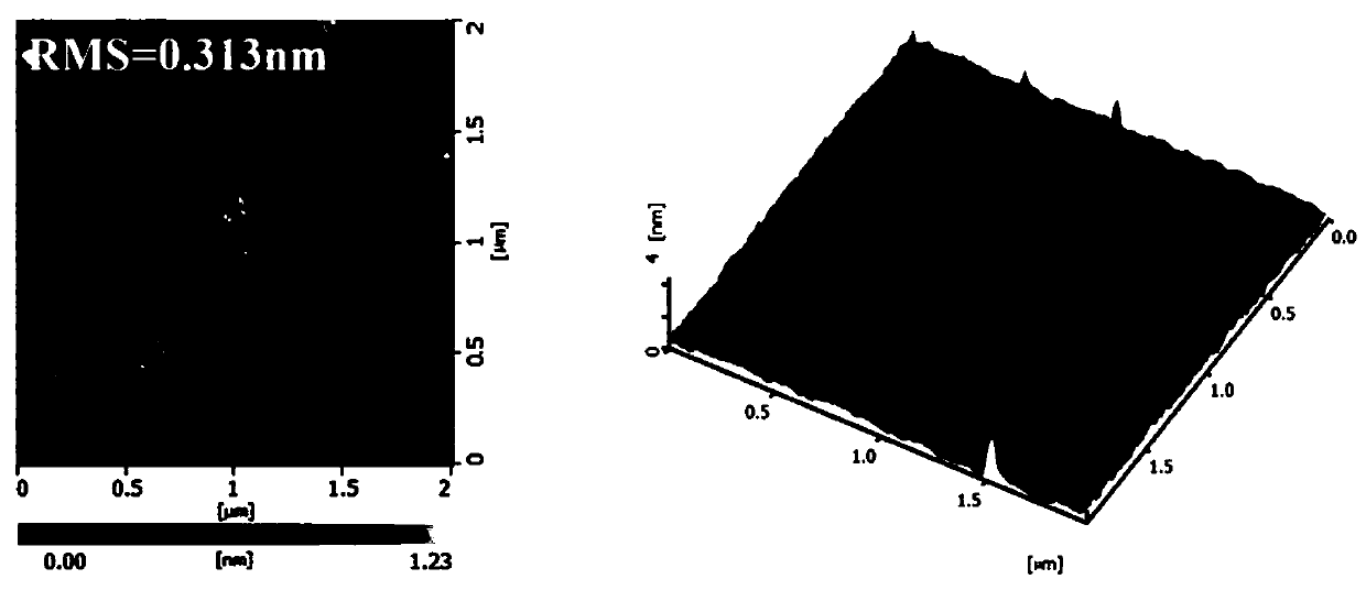
[0042] MoS 2 After the quantum dot solution is spin-coated on the surface of the PEDOT:PSS layer, the second annealing is performed to obtain MoS 2 quantum dot layer;

[0043] In the MoS 2 On the surface of the quantum dot layer, a hole transport layer, a light-emitting layer, an electron transport layer, an electron injection layer and an electrode layer are vapor-deposited in sequence to obtain an organic light-emitting diode.

[0044] In the present invention, after the PEDOT:PSS solution is spin-coated on the surface of the ITO substrate, the first annealing is performed to obtain the PEDOT:PSS layer; the solvent of the PEDOT:PSS solution...

Embodiment 1

[0067] After the 150nm thick ITO substrate is cleaned and dried, it is treated with ultraviolet light for 5 minutes, and then left to stand for 10 minutes to obtain a pretreated ITO substrate;

[0068] Adjust the working parameters of the KW-4 spin coater (rotating speed is 3000rpm, time is 60s), place the ITO substrate on the sheet holder of the KW-4 spin coater, fix the ITO substrate by vacuum suction, and pipette The gun sucks the PEDOT:PSS solution, and the tip of the gun is about 3cm away from the ITO substrate. After dropping the PEDOT:PSS solution on the ITO substrate, quickly start the KW-4 spin coater for spin coating; after the spin coating is completed, at 130°C Anneal for 15 minutes, cool to get PEDOT:PSS layer (30nm);

[0069] According to the above spin-coating and annealing process, MoS was prepared on the surface of PEDOT:PSS layer 2 Quantum dot layer (20nm) (the difference is: MoS 2 The concentration of the quantum dot solution is 12mg / mL, and the annealing ...

Embodiment 2

[0073] After the 150nm thick ITO substrate is cleaned and dried, it is treated with ultraviolet light for 5 minutes, and then left to stand for 10 minutes to obtain a pretreated ITO substrate;

[0074] Adjust the working parameters of the KW-4 spin coater (rotating speed is 3000rpm, time is 60s), place the ITO substrate on the sheet holder of the KW-4 spin coater, fix the ITO substrate by vacuum suction, and pipette The gun sucks the PEDOT:PSS solution, and the tip of the gun is about 3cm away from the ITO substrate. After dropping the PEDOT:PSS solution on the ITO substrate, quickly start the KW-4 spin coater for spin coating; after the spin coating is completed, at 130°C Anneal for 15 minutes, cool to get PEDOT:PSS layer (30nm);

[0075] According to the above spin-coating and annealing process, MoS was prepared on the surface of PEDOT:PSS layer 2Quantum dot layer (25nm) (the difference is: MoS 2 The concentration of the quantum dot solution is 15mg / mL, and the annealing t...


PUM


Abstract

The invention relates to the technical field of light-emitting diodes, and particularly relates to an organic light-emitting diode and a preparation method thereof. The organic light-emitting diode provided by the invention comprises an ITO substrate, a hole injection layer, a hole transport layer, a light emitting layer, an electron transport layer, an electron injection layer and an electrode layer, wherein the hole injection layer includes a PEDOT: PSS layer and an MoS2 quantum dot layer. The hole injection ability of the organic light-emitting diode (OLED) is mainly enhanced through the MoS2 quantum dot layer. Meanwhile, the MoS2 quantum dot layer can prevent the PEDOT: PSS layer from absorbing moisture, so that the stability of the organic light-emitting diode device is improved. According to the embodiment, the maximum current efficiency of the light-emitting diode device in the invention can reach up to 73.5cd.A<-1>, which is greatly improved compared with the maximum current efficiency (60.2cd.A<-1>) in the prior art.

Description

technical field [0001] The invention relates to the technical field of light emitting diodes, in particular to an organic light emitting diode and a preparation method thereof. Background technique [0002] In recent years, organic light-emitting diodes (OLEDs) have been widely used in actual production and life, especially in the field of folding screen displays. Compared with traditional inorganic electroluminescent devices, their research, preparation and application have become the One of the most active areas of research. [0003] As a production technology, the preparation of organic light-emitting diode (OLED) devices by solution method has the advantages of simple operation, high material utilization rate and low cost. Since the energy level difference between the common anode electrode material and the light-emitting layer material is relatively obvious, in order to improve the efficiency of OLED devices, it is usually necessary to insert a hole injection layer bet...

Claims


Application Information

Patent Timeline
Patent Type & Authority Applications(China)
IPC IPC(8): H01L51/50H01L51/56
CPCH10K71/12H10K71/40H10K50/115H10K50/17
Inventor 万敏强朱文清王梦狄刘丹石冠杰张沛殷正元
Owner SHANGHAI UNIV
Why Eureka
Try Eureka