Embedded disk motor stator coil assembling apparatus control system

A control system and disc motor technology, applied in the control system, the control of the speed or torque of the motor, and the manufacture of motor generators, etc. Signal detection module monitoring and other issues, to achieve the effect of low cost, reduced failure rate, and fast processing speed

Pending Publication Date: 2019-07-05
江苏科瑞德智控自动化科技有限公司 +1
View PDF7 Cites 0 Cited by
  • Summary
  • Abstract
  • Description
  • Claims
  • Application Information

AI Technical Summary

Problems solved by technology

At present, most of the stator processing processes are to roll the copper wire into the wire mold, and then manually embed the copper coil into the motor core. This processing method has low efficiency, high requirements for manual skills, and loose artificial wire embedding. Disadvantages, affecting stator performance
[0003] Existing wire embedding machine control systems mostly use PLC control, which requires PLC to control multiple motors. PLC can select speed mode, position mode, and torque mode. In actual work, each motor only needs to select one mode. Yes; the control of the solenoid valve only needs to be controlled by the switching value. In addition to the switching value control, the PLC also has unnecessary functions such as monitoring and fault feedback, which will cause redundant PLC functions, increase system development costs, and the wiring process is cumbersome. The cabinet is bulky, which is not conducive to the miniaturization and light weight of the equipment
[0004] The document with application number 201410393730.2 discloses a semi-automatic horizontal wire inserting machine, which has a single function and lacks the monitoring of the motor shaft in the system; at the same time, it lacks a signal detection module to monitor the wire inserting machine during the production process, and cannot The quality of the motor stator is monitored in real time during the production process, which cannot provide reference indicators for subsequent production

Method used


Image

  • Embedded disk motor stator coil assembling apparatus control system
  • Embedded disk motor stator coil assembling apparatus control system
  • Embedded disk motor stator coil assembling apparatus control system

Examples


Embodiment Construction

[0026] Specific examples of the present invention are given below. The specific embodiments are only used to further describe the present invention in detail, and do not limit the protection scope of the claims of the present application.

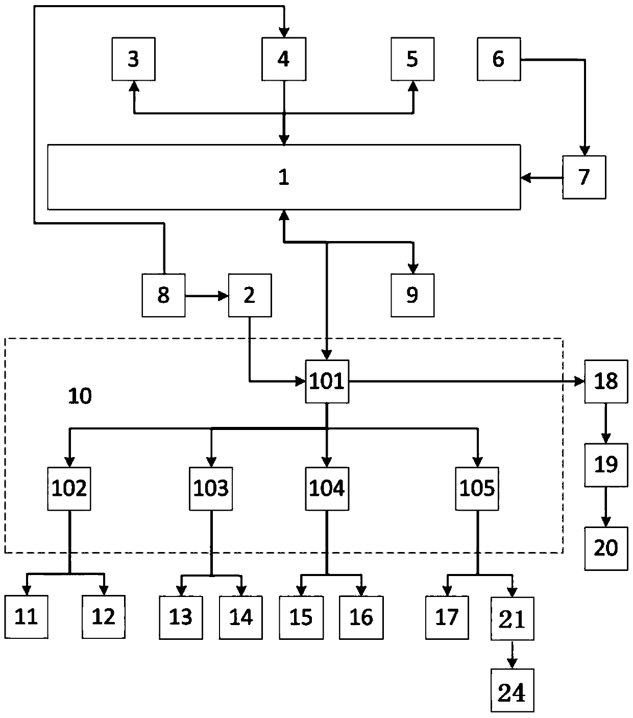
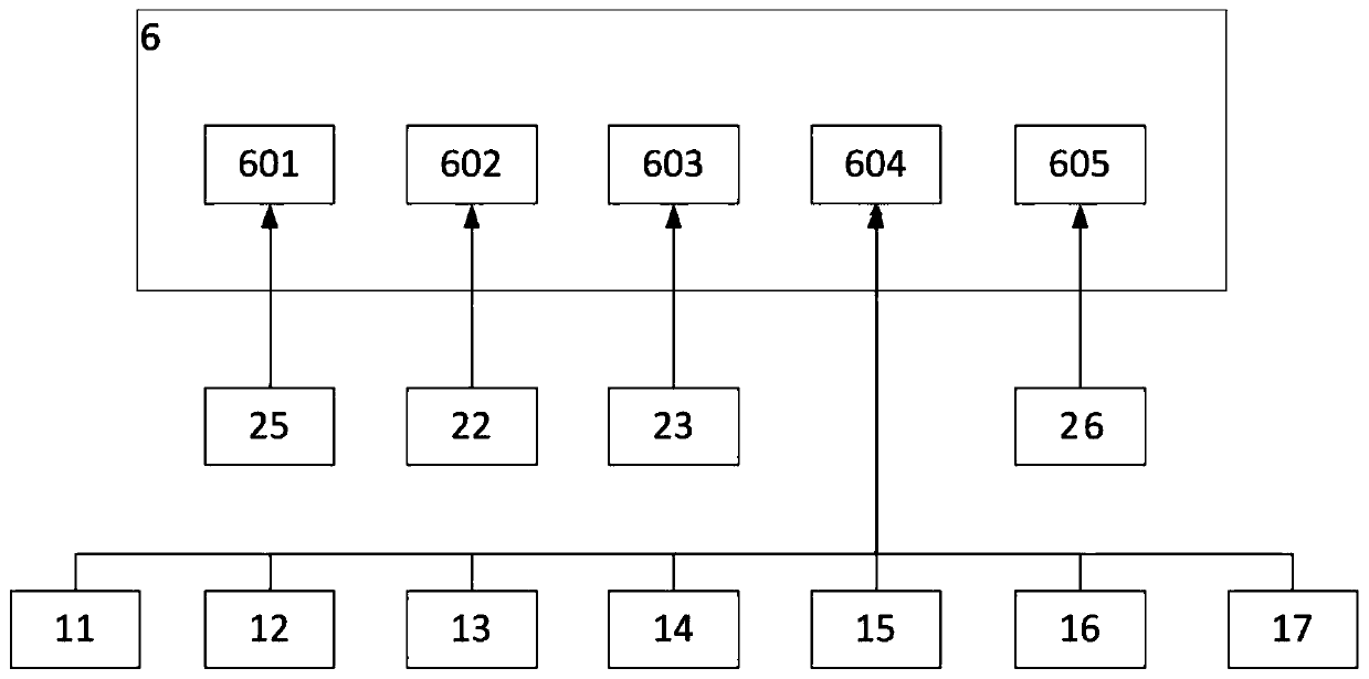
[0027] The invention provides a control system based on an embedded disc motor stator wire inserting machine (control system for short), which is characterized in that the control system includes a single-chip microcomputer 1, an FPGA module analog power input circuit 2, a single-chip power conversion module 4, a human Machine interaction module 5, signal detection module 6, input switch signal optocoupler isolation circuit 7, FPGA power conversion module 8, data storage module 9 and FPGA module 10; Said FPGA module 10 includes FPGA chip 101, first motor drive circuit 102 , the second motor drive circuit 103, the third motor drive circuit 104 and the fourth motor drive circuit 105;

[0028] The single-chip microcomputer 1 is electrically c...


PUM


Abstract

The invention discloses an embedded disk stator coil assembling apparatus control system. The embedded disk motor stator coil assembling apparatus control system comprises a single-chip microcomputer,a FPGA (Field Programmable Gate Array) module simulation power input circuit, a single-chip power conversion module, a human-machine interaction module, a signal detection module, an input switch signal optocoupler isolation circuit, a FPGA power conversion module, a data storage module, a FPGA module, wherein the FPGA module comprises a FPGA chip, a first motor-driven circuit, a second motor-driven circuit, a third motor-driven circuit and a fourth motor-driven module. The control system performs modular design according to the functions needing to be implemented by the coil assembling apparatus, so that the system can be more stable; equipment minimalization and lightweight are facilitated; the equipment stability can be improved; and the defects of heavy weight and low stability of theconventional equipment can be overcome.

Description

technical field [0001] The invention relates to the field of mechanical control systems, in particular to a control system for an embedded disc motor stator wire inserting machine. Background technique [0002] The wire embedding machine is a mechanical production equipment for embedding the iron core of the motor into the coil. At present, most of the stator processing processes are to roll the copper wire into the wire mold, and then manually embed the copper coil into the motor core. This processing method has low efficiency, high requirements for manual skills, and loose artificial wire embedding. Disadvantages affect the performance of the stator. [0003] Existing wire embedding machine control systems mostly use PLC control, which requires PLC to control multiple motors. PLC can select speed mode, position mode, and torque mode. In actual work, each motor only needs to select one mode. Yes; the control of the solenoid valve only needs to be controlled by the switchi...

Claims


Application Information

Patent Timeline
Patent Type & Authority Applications(China)
IPC IPC(8): H02P5/00H02K15/08
CPCH02P5/00H02K15/08
Inventor 肖艳军高静孟召宗万峰周围
Owner 江苏科瑞德智控自动化科技有限公司
Why Eureka
Try Eureka