Driving structure and device with flexible joint

A technology of flexible joints and driving structures, applied in the field of medical devices, can solve problems such as large operating space, and achieve the effects of good comfort, convenient processing and manufacturing, and stable hinge structure

Active Publication Date: 2019-07-09
精勤智造(苏州)医疗科技有限公司
View PDF9 Cites 4 Cited by
  • Summary
  • Abstract
  • Description
  • Claims
  • Application Information

AI Technical Summary

Problems solved by technology

[0005] Therefore, the technical problem to be solved by the present invention is that the existing minimally invasive surgical forceps requires a large operating space when operating the flexible joint rotation, which affects the use of other surgical operatin

Method used


Image

  • Driving structure and device with flexible joint
  • Driving structure and device with flexible joint
  • Driving structure and device with flexible joint

Examples


Embodiment 1

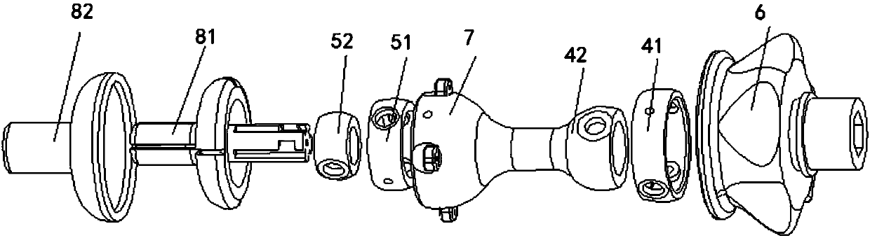
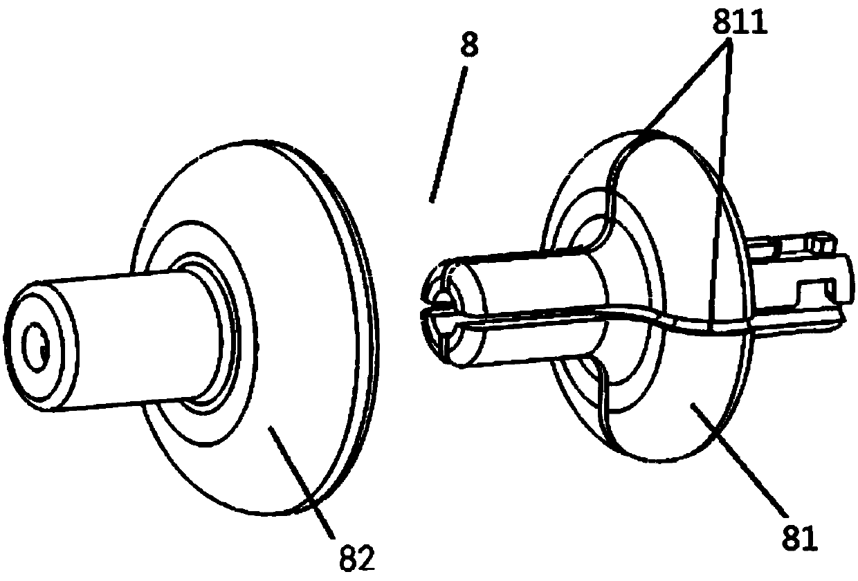
[0048] The driving structure 9 of the present embodiment, such as figure 1 , image 3 , Figure 4 As shown, it is suitable for application in devices with flexible joints, and the device with flexible joints includes flexible joints 33 and a grip part 2 . The driving structure 9 includes a driving body 1 and a control line 10 .

[0049] The driving body 1 is arranged between the flexible joint 33 and the grip part 2, and its two ends are respectively connected with the flexible joint 33 and the grip part 2, and the two ends of the driving body 1 can be relatively deflected.

[0050] One end of the control wire 10 is connected to an end of the flexible joint 33 away from the driving body 1 , and the other end is connected to the driving body 1 . The two ends of the driving body 1 deflect relative to each other, and the distance between the connection between the flexible joint 33 and the control wire 10 and the connection between the driven body 1 and the control wire 10 cha...

Embodiment 2

[0062] In this embodiment, on the basis of Embodiment 1, the driving structure 9 also includes a runner 6, which is rotatably connected to the grip part 2, and can drive the driving body 1 to rotate around the axis of the driving body 1, and the driving body 1 passes through the first Hinged shaft and runner 6 are hinged. In order to make the rotation speed of the runner 6 consistent with the rotation speed of the actuator, the axis of the runner 6 coincides with the axis of the actuator 3 .

[0063] In this embodiment, the specific structure is that the first hinge member 51 is hinged in the runner 6 through the first hinge shaft.

Embodiment 3

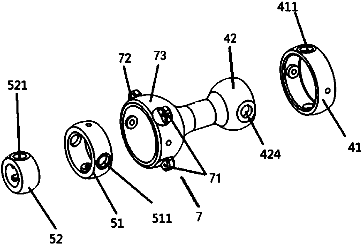
[0065] This embodiment is on the basis of embodiment 1, as figure 2 , Figure 5 , Figure 6 As shown, the driving body 1 further includes a second Hooke hinge structure 4 disposed between the first Hooke hinge structure 5 and the grip part 2 . The second Hookee hinge structure 4 includes a third hinge part 41 and a fourth hinge part 42 . The third hinge 41 is provided with a third hinge hole 411, the third hinge hole 411 is provided with a third bearing whose axis coincides with the axis of the third hinge hole 411, and the third hinge shaft is arranged on the third hinge through the third bearing. 41, the third hinge member 41 is hinged in the grasping part 2 through the third hinge shaft. One end of the fourth hinge 42 is provided with a fourth hinge hole 424, the fourth hinge hole 424 is provided with a fourth bearing whose axis coincides with the axis of the fourth hinge hole 424, and the fourth hinge shaft is arranged on the fourth hinge through the fourth bearing. O...


PUM


Abstract

The invention relates to the technical field of medical instruments, in particular to a driving structure and a device with a flexible joint. The driving structure comprises a driving body and a control line, the driving body is arranged between the flexible joint and a holding portion, two ends of the driving body are connected with the flexible joint and the holding portion, the two ends of thedriving body can relatively and eccentrically rotate, one end of the control line is connected with one end, far away from the driving body, of the flexible joint, the other end of the control line isconnected with the driving body, the two end of the driving body relatively and eccentrically rotate, the distance between a joint of the flexible joint and the control line and a joint of the driving body and the control line is changed, so that the control line draws the flexible joint to rotate. The device with the flexible joint comprises the driving structure, the holding portion and the flexible joint. According to the driving structure and the device with the flexible joint, when rotation of the flexible joint is operated, needed operation space is small, and use of the other operationdevices cannot be affected.

Description

technical field [0001] The invention relates to the technical field of medical instruments, in particular to a driving structure and a device with flexible joints. Background technique [0002] Minimally invasive surgery is the most cutting-edge development direction of medical technology today. Because of its small surgical trauma, mild postoperative pain, short hospital stay, and fast wound healing, it has been widely used clinically and achieved satisfactory results. [0003] At present, the international patent document WO2017062529A1 in the prior art includes a flexible joint, a grip part, a joint control part and a bracket. One end of the support is connected with a flexible joint, and the other end is provided with a joint control part for controlling the rotation of the flexible joint. The holding part is arranged between the flexible joint and the joint control part and is connected with the other end of the support. [0004] In the above-mentioned patent documents...

Claims


Application Information

Patent Timeline
IPC IPC(8): A61B17/00A61B17/29
CPCA61B17/00234A61B17/29A61B17/2909A61B2017/00367A61B2017/2901
Inventor 王屹初徐欣良宜李晓贞
Owner 精勤智造(苏州)医疗科技有限公司
Why Eureka
Try Eureka