
Differential shell automatic production line

A technology for automated production lines and differentials, which is applied to other manufacturing equipment/tools, metal processing machinery parts, maintenance and safety accessories, etc. It can solve problems such as parts bumping, damage to the contact surface of the material rack, and difficulty in cleaning, saving manpower The effect of resources, reliable safety guarantee and production cost saving

Pending Publication Date: 2019-07-09
郧西精诚汽配有限公司
View PDF0 Cites 3 Cited by
  • Summary
  • Abstract
  • Description
  • Claims
  • Application Information

AI Technical Summary

Problems solved by technology

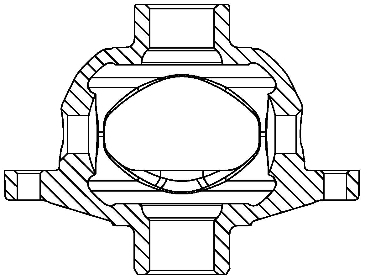
[0002] see figure 1 As shown, the manual production line is mainly used to produce the differential case at present. The manual production line consists of 3 horizontal lathes, 1 vertical lathe, 1 vertical lathe, 1 vertical milling machine, and 1 special machine. There are 7 production sequences in total. , Each shift requires 7 production workers. The material transfer rack between the processes uses a trolley, and the parts loading and unloading on the machine tool and the transfer of the parts on the rack are carried out manually. It is easy to cause the parts to bump and damage the contact surface with the rack. Product quality, and the labor intensity of operators is relatively high; the production equipment is arranged in a straight line, it is difficult to realize one person to operate multiple machines, resulting in waste of labor and resources; the human influence of the placement of material trolleys between processes is relatively large, in The uncontrollable state leads to chaos and disorder; although the machine tool is equipped with a pneumatic blow gun and a chip box for receiving iron chips, it is difficult to ensure the cleanliness of the workshop. On the ground, it is not only difficult to clean but also easy to slip, posing a safety hazard

Method used


Image

  • Differential shell automatic production line
  • Differential shell automatic production line
  • Differential shell automatic production line

Examples


Embodiment Construction

[0032] Embodiments of the present invention are described in detail below, examples of which are shown in the drawings, wherein the same or similar reference numerals represent the same or similar elements or elements having the same or similar functions throughout.

[0033] In the description of the present invention, it should be noted that for orientation words, such as the term "center", "horizontal (X)", "longitudinal (Y)", "vertical (Z)", "length", " Width", "Thickness", "Top", "Bottom", "Front", "Back", "Left", "Right", "Vertical", "Horizontal", "Top", "Bottom", "Inner ", "outside", "clockwise", "counterclockwise" and other indication orientations and positional relationships are based on the orientation or positional relationship shown in the drawings, and are only for the convenience of describing the present invention and simplifying the description, rather than indicating or implying the Means that a device or element must have a specific orientation, be constructed...


PUM


Abstract

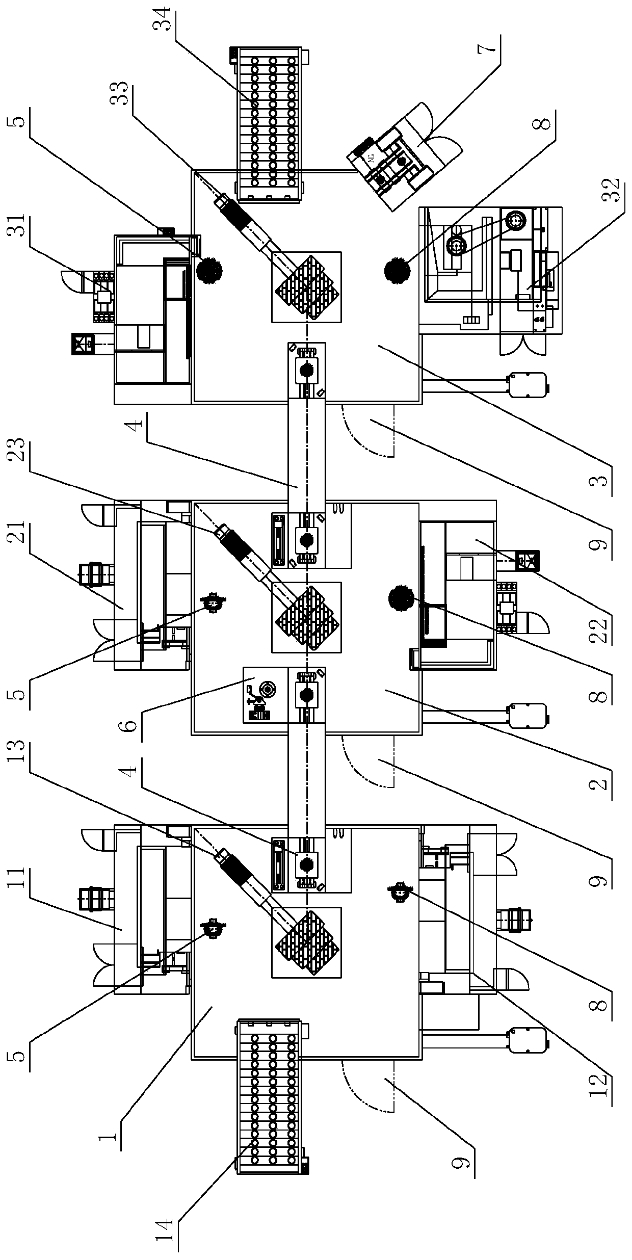
The invention discloses a differential shell automatic production line, and relates to the technical field of automobile part machining and manufacturing. The differential shell automatic production line comprises a feeding line, a first workbench, a second workbench, a third workbench and a discharging line which are arranged in sequence; the differential shell automatic production line further comprises a first processing device, a second processing device, a third processing device, a fourth processing device, a fifth processing device, a sixth processing device and two transfer stock bins,wherein one transfer stock bin is arranged between the first workbench and the second workbench, and the other one transfer stock bin is arranged between the second workbench and the third workbench;the differential shell automatic production line is used for realizing transferring of the differential mechanism shell between every two adjacent workbenches; a first robot is arranged on the firstworkbench, and the first robot is used for grabbing and transferring the differential shell; the second workbench is provided with a second robot, and the second robot is used for grabbing and transferring the differential shell; and the third workbench is provided with a third robot, and the third robot is used for grabbing and transferring the differential shell.

Description

technical field [0001] The invention relates to the technical field of auto parts processing and manufacturing, in particular to an automatic production line for a differential case. Background technique [0002] see figure 1 As shown, the manual production line is mainly used to produce the differential case at present. The manual production line consists of 3 horizontal lathes, 1 vertical lathe, 1 vertical lathe, 1 vertical milling machine, and 1 special machine. There are 7 production sequences in total. , Each shift requires 7 production workers. The material transfer rack between the processes uses a trolley, and the parts loading and unloading on the machine tool and the transfer of the parts on the rack are carried out manually. It is easy to cause the parts to bump and damage the contact surface with the rack. Product quality, and the labor intensity of operators is relatively high; the production equipment is arranged in a straight line, it is difficult to realize ...

Claims


Application Information

Patent Timeline
Patent Type & Authority Applications(China)
IPC IPC(8): B23P23/06B23Q7/04B23Q11/00
CPCB23P23/06B23Q7/048B23Q11/005
Inventor 舒宗敏张一兵喻培虎
Owner 郧西精诚汽配有限公司
Learn More