
SMC workpiece surface treatment method and application thereof

A technology for surface treatment and parts, which is applied to devices and coatings that apply liquid to the surface. It can solve problems such as insufficient adhesion, poor surface of parts, and FRP cracking and peeling, so as to reduce the complexity and improve the protection effect. , Accurately correct the effect of lifting

Active Publication Date: 2019-07-09
杭州比亚迪汽车有限公司
View PDF4 Cites 0 Cited by
  • Summary
  • Abstract
  • Description
  • Claims
  • Application Information

AI Technical Summary

Problems solved by technology

For vehicles, SMC composite materials are currently mainly used to make body, bumper, interior products, etc. After the bumper is installed, there are usually parts that match the surrounding parts due to various reasons such as structural design and assembly operation. Face difference
The existing surface correction process generally adopts: grinding, resin brushing, puttying, secondary puttying, grinding, pasting of glass fiber felt and multiple grindings after curing; the whole correction process is cumbersome and requires a , environmental requirements, and operational requirements are high. Taking grinding as an example, the bumper (specifically, SMC parts) needs to be fully polished many times by using the existing surface difference correction process, but it is limited by the characteristics of the SMC parts itself, that is, : The molecular structure is tight, the surface has no micropores, and the bumper body after multiple times of full polishing still cannot meet the surface roughness requirements of hand-laid FRP, and it is difficult to form an effective bond between the paper glass fiber mat and the bumper body , there are often pasting defects and insufficient adhesion after pasting, which lead to cracking and falling off of FRP, and the defect rate is as high as 30%, which seriously affects the appearance quality and processing cost

Method used

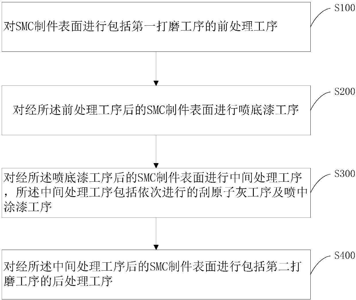
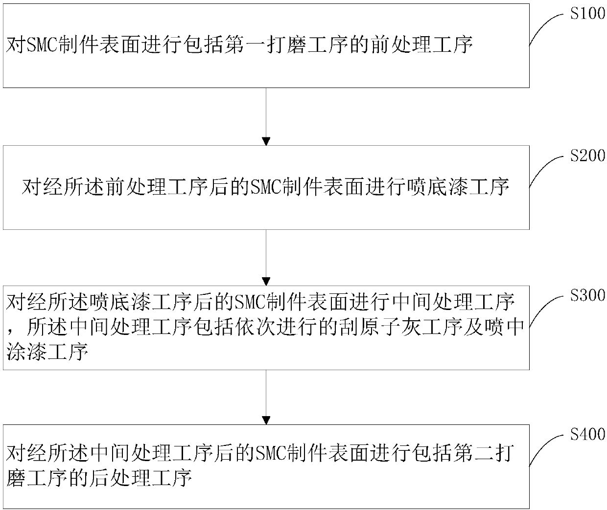

Image

  • SMC workpiece surface treatment method and application thereof
  • SMC workpiece surface treatment method and application thereof

Examples


Embodiment Construction

[0025] In order to make the technical problems, technical solutions and beneficial effects to be solved by the present invention clearer, the present invention will be further described in detail below in conjunction with the accompanying drawings and embodiments. It should be understood that the specific embodiments described here are only used to explain the present invention, not to limit the present invention.

[0026] In the description of the present invention, it should be understood that the terms "first" and "second" are used for description purposes only, and cannot be interpreted as indicating or implying relative importance or implicitly indicating the quantity of indicated technical features. Thus, a feature defined as "first" and "second" may explicitly or implicitly include one or more of these features. In the description of the present invention, "plurality" means two or more, unless otherwise specifically defined.

[0027] It is to be understood that the ter...


PUM

PropertyMeasurementUnit
Thicknessaaaaaaaaaa

Abstract

The invention provides an SMC workpiece surface treatment method and a method for correcting the surface difference of a vehicle bumper by applying the method. The SMC workpiece surface treatment method comprises the following steps: carrying out a pretreatment process including a first polishing process on the surface of an SMC workpiece; carrying out a primer spraying process on the surface of the SMC workpiece after the pretreatment process; carrying out an intermediate treatment process on the surface of the SMC product after the primer spraying process, wherein the intermediate treatmentprocess comprises a putty scraping process and a floating coat spraying process which are carried out in sequence; and performing a post-treatment process including a second polishing process on the surface of the SMC product after the intermediate treatment process. According to the method, an atomic ash scraping process is adopted to replace a glass fiber reinforced plastic pasting process in the prior art; and intermediate paint is adopted to replace resin in the prior art to serve as an intermediate connecting medium, the complexity of the whole technological process is reduced, the surface treatment quality can be improved while accurate correction of the surface of the SMC workpiece is achieved, and the adhesive force of a surface coating of the SMC workpiece is remarkably improved.

Description

technical field [0001] The invention relates to the field of surface treatment, in particular to a method for surface treatment of SMC parts and a method for correcting the surface difference of a vehicle bumper by applying the method. Background technique [0002] SMC (Sheet molding compound) composite materials are often used to make machine parts, vehicles, ships, etc. because of their excellent electrical insulation properties, mechanical properties, thermal stability and chemical corrosion resistance. For vehicles, SMC composite materials are currently mainly used to make body, bumper, interior products, etc. After the bumper is installed, there are usually parts that match the surrounding parts due to various reasons such as structural design and assembly operation. Face difference phenomenon. The existing surface correction process generally adopts: grinding, resin brushing, puttying, secondary puttying, grinding, pasting of glass fiber felt and multiple grindings af...

Claims


Application Information

Patent Timeline
IPC IPC(8): B24B1/00B05D7/00
CPCB05D7/584B24B1/00
Inventor 郑涛
Owner 杭州比亚迪汽车有限公司
Features
  • Generate Ideas
  • Intellectual Property
  • Life Sciences
  • Materials
  • Tech Scout
  • Unparalleled Data Quality
  • Higher Quality Content
  • 60% Fewer Hallucinations
Learn More