A tandem pulse tube refrigerator
A pulse tube refrigerator, tandem technology, applied in refrigerators, refrigeration and liquefaction, compressors, etc., to achieve the effect of reducing length, compact structure, and small mechanical loss
- Summary
- Abstract
- Description
- Claims
- Application Information
AI Technical Summary
Problems solved by technology
Method used
Image
Examples
Embodiment 1
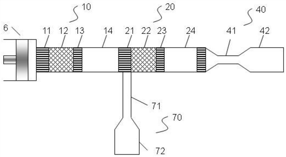
[0029] Such as figure 1 As shown, this embodiment is a two-stage tandem pulse tube refrigerator, and the first pulse tube refrigerator unit 10 includes a first radiator 11, a first regenerator 12, a first cooling capacity heat exchanger 13, a first Vessels14. The first pulse tube is then connected to the second pulse tube refrigerator unit 20 , which includes a second radiator 21 , a second regenerator 22 , a second cooling heat exchanger 23 and a second pulse tube 24 . The second vessel 24 is connected to a terminal phase regulator 40, which includes a terminal inertial tube 41 and a terminal gas reservoir 42. The terminal phase regulator 40 can make the second regenerator 22 work in a better phase. The hot end of the first pulse tube 14 of the first pulse tube refrigerator unit 10 is connected to the first phase modulator 70 , including a first inertia tube 71 and a first gas bank 72 . The first inertia tube 71 is connected to the hot end of the first pulse tube 14 to adju...
Embodiment 2
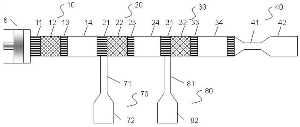
[0032] Such as figure 2 As shown, the present embodiment is a three-stage tandem pulse tube refrigerator to further utilize the expansion work of the second pulse tube refrigerator unit 20 . In this embodiment, on the basis of Embodiment 1, a third pulse tube refrigerator unit 30 is added between the terminal phase modulator 40 and the second pulse tube refrigerator unit 20, including a third radiator 31 and a third regenerator. 32 , the third cooling heat exchanger 33 , and the third vessel 34 . The third radiator 31 dissipates heat, and the third cooling heat exchanger 33 obtains cold energy, and the hot end of the third pulse tube 34 is connected to the second phase modulator 80, including the second inertia tube 81 and the second air reservoir 82 The second inertia tube 81 is connected to the hot end of the second pulse tube 24 so as to adjust the phase of the second-stage regenerator 22 to obtain a proper phase to obtain high heat recovery efficiency and further reduce ...
Embodiment 3
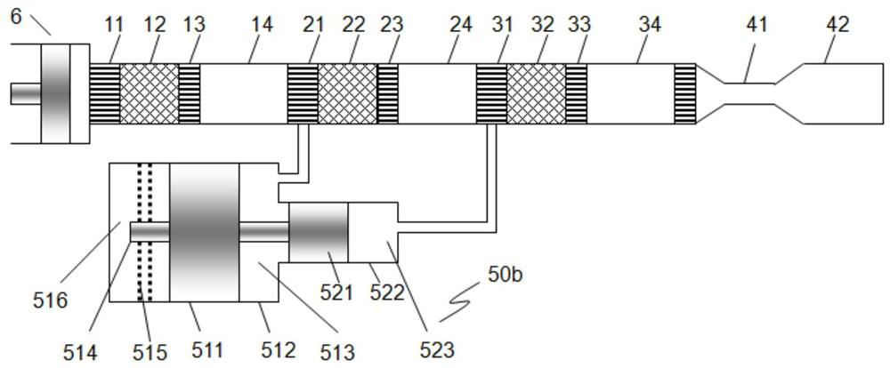
[0034] Such as image 3 In this embodiment, the first phase modulator 70 and the second phase modulator 80 in Embodiment 2 are replaced by a stepped solid phase modulator 50b, including a two-stage push piston 521, a two-stage cylinder 522 and a second formed The front cavity 523, the push piston 511 and the spring 514 form a vibration system in the cylinder 512. The front cavity 513 is connected to the hot end of the first vessel 14, and the push piston 511 vibrates under the pressure difference between the front cavity 513 and the back cavity 516. The second front cavity 523 is connected to the hot end of the second vessel 24 so as to adjust the phase of the second-stage regenerator 22 to obtain a proper phase to obtain high heat recovery efficiency and further reduce heat recovery loss.
[0035] Since the pulse tube units are directly connected, the work of the previous pulse tube refrigerator unit is directly transmitted to the latter unit, so there is no transmission loss...
PUM
 Abstract
Description
Claims
Application Information
 - R&D
- Intellectual Property
- Life Sciences
- Materials
- Tech Scout
- Unparalleled Data Quality
- Higher Quality Content
- 60% Fewer Hallucinations
Browse by: Latest US Patents, China's latest patents, Technical Efficacy Thesaurus, Application Domain, Technology Topic, Popular Technical Reports.
© 2025 PatSnap. All rights reserved.Legal|Privacy policy|Modern Slavery Act Transparency Statement|Sitemap|About US| Contact US: help@patsnap.com


