
Visual positioning method and device

A technology of visual positioning and location points, applied in the field of computer vision, can solve the problems of high integration, low scalability, and difficulty in implementation, and achieve the effects of high integration, strong scalability, and cost reduction.

Active Publication Date: 2019-07-09
北京易达图灵科技有限公司
View PDF14 Cites 12 Cited by
  • Summary
  • Abstract
  • Description
  • Claims
  • Application Information

AI Technical Summary

Problems solved by technology

However, most of the multi-line lidars are more than 10cm*10cm*10cm. Due to their large size, they can only be deployed on larger platforms, and it is difficult to achieve a high degree of integration.
In addition, the lidar data is relatively simple, only spatial distance information, and the scalability is not strong
If applications such as image detection, image recognition, etc. are required, additional camera sensors must be installed

Method used


Image

  • Visual positioning method and device
  • Visual positioning method and device
  • Visual positioning method and device

Examples


Embodiment Construction

[0015] In order to make the purpose, technical solutions and advantages of the embodiments of the present invention clearer, the technical solutions in the embodiments of the present invention will be clearly and completely described below in conjunction with the drawings in the embodiments of the present invention. Obviously, the described embodiments It is a part of embodiments of the present invention, but not all embodiments. Based on the embodiments of the present invention, all other embodiments obtained by persons of ordinary skill in the art without creative efforts fall within the protection scope of the present invention.

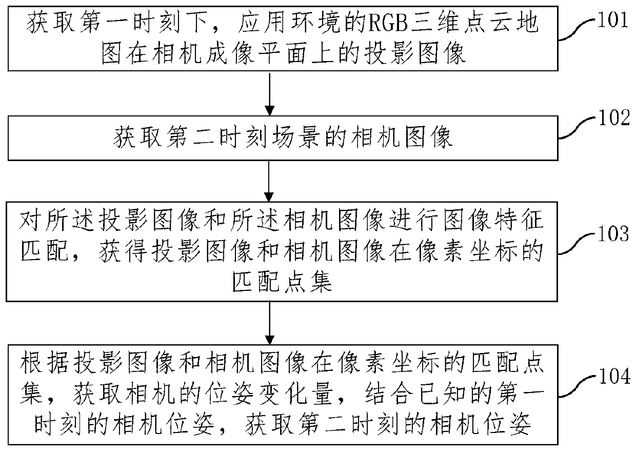
[0016] At present, the visual positioning method with high accuracy is realized by using multi-line lidar. However, multi-line lidar is relatively expensive, bulky and not very scalable.

[0017] To solve this problem, an embodiment of the present invention provides a visual positioning method. This method can be applied to the scenarios where r...


PUM


Abstract

The embodiment of the invention provides a visual positioning method and device, and the method comprises the steps: obtaining a projection image of an RGB three-dimensional point cloud map of an application environment on a camera imaging plane at a first moment; obtaining a camera image of the scene at the second moment; performing image feature matching on the projection image and the camera image to obtain a matching point set of the projection image and the camera image in pixel coordinates; according to the matching point set of the projection image and the camera image in the pixel coordinates, acquiring the pose variation of the camera and combinding the known camera pose at the first moment to obtain the camera pose at the second moment. The method has high precision. Through lowcost and high precision, cost of the visual positioning device is effectively reduced. The camera is used as a sensor. More applications can be developed under the condition that the sensor is not added, and high expansibility is achieved. Finally, due to the high integration level of the existing camera module, the light weight and miniaturization of the positioning device can be realized.

Description

technical field [0001] Embodiments of the present invention relate to the field of computer vision, and in particular, to a visual positioning method and device. Background technique [0002] Visual positioning has been widely used in various fields, such as industrial robots, service robots, unmanned driving and so on. Taking the robot as an example, in order to understand the working conditions of the robot, it is necessary to locate the robot in real time, so as to obtain the walking route and location of the robot. [0003] At present, the visual positioning method with high accuracy uses multi-line lidar and locates through the established 3D point cloud map. First obtain the 3D point cloud map according to the 3D laser scanner, and then use the spatial information of the 3D point cloud to match and locate the multi-line lidar sensor data, and repeatedly calculate the distance between each moment and the previous moment during the movement of the lidar. Position devia...

Claims


Application Information

Patent Timeline
Patent Type & Authority Applications(China)
IPC IPC(8): G06T7/70
CPCG06T7/70
Inventor 王毓玮刘洋华仁红尚云冯卓玉
Owner 北京易达图灵科技有限公司
Features
  • Generate Ideas
  • Intellectual Property
  • Life Sciences
  • Materials
  • Tech Scout
  • Unparalleled Data Quality
  • Higher Quality Content
  • 60% Fewer Hallucinations
Learn More