An automatic conveying line for processing molded wire-wound inductors

A technology of automatic transportation and inductors, which is applied in the manufacture of inductors/transformers/magnets, circuits, electrical components, etc., can solve the problems of high degree of work automation, low work efficiency, and high output output, and achieve high work automation and work efficiency. The effect of high output and high output

Active Publication Date: 2020-11-10
耒阳市铭博电子有限公司
View PDF9 Cites 0 Cited by
  • Summary
  • Abstract
  • Description
  • Claims
  • Application Information

AI Technical Summary

Problems solved by technology

[0004] The purpose of the present invention is to address the deficiencies of the prior art, by setting the first feeding mechanism to load the coil, the second feeding mechanism to load the magnetic core, and then using the transmission mechanism and the circulation mechanism to connect the coil and the magnetic core. At the same time, through the synchronous and reverse work of the transmission mechanism up and down and the automatic 180° station conversion of the circulation mechanism, it solves the technical problems of manual operation, low work efficiency and low production capacity in the bonding and forming process. Realize the cycle of feeding, molding and discharging and use it continuously. Its work has a high degree of automation and high output output

Method used


Image

  • An automatic conveying line for processing molded wire-wound inductors
  • An automatic conveying line for processing molded wire-wound inductors
  • An automatic conveying line for processing molded wire-wound inductors

Examples


Embodiment 1

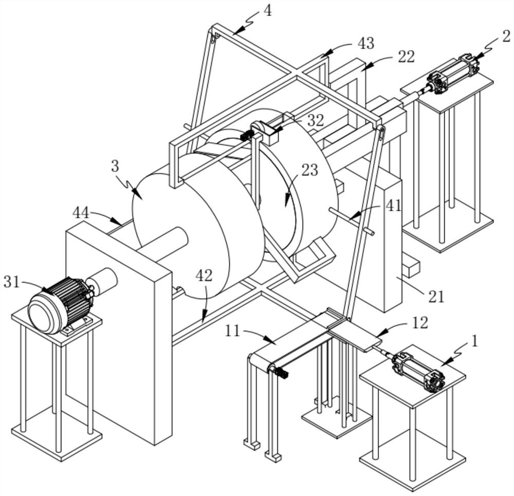
[0069] Such as figure 1 , Figure 8 and Figure 9 As shown, an automatic conveying line for processing molded wire wound inductors, including:

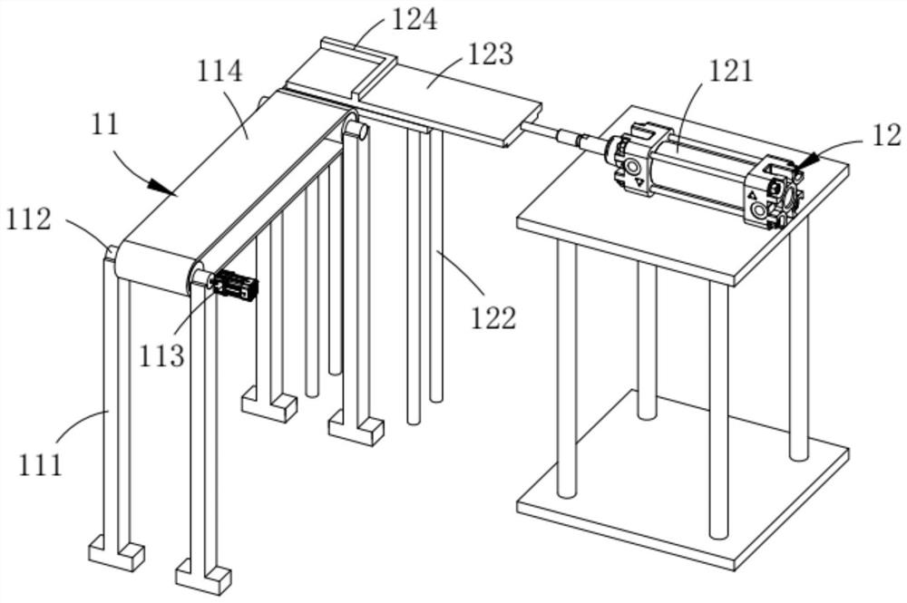
[0070] The first feeding mechanism 1, the first feeding mechanism 1 includes a transmission assembly 11 and a pneumatic assembly a12 arranged at the output end of the transmission assembly 11 and perpendicular to the transmission assembly 11;

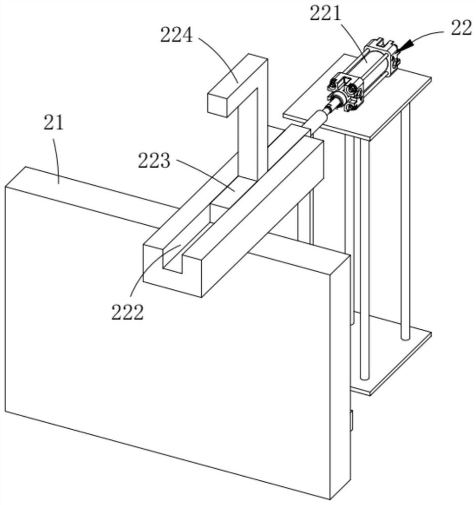
[0071] The second feeding mechanism 2, the second feeding mechanism 2 includes a frame 21 arranged in the direction of the output end of the pneumatic assembly a12, a pneumatic assembly b22 slidably arranged on the frame 21 and fixedly arranged on the The storage assembly 23 at the output end of the pneumatic assembly b22;

[0072] A circulation mechanism 3, the circulation mechanism 3 includes a revolving assembly 31 rotatably arranged on the storage assembly 23 and a gluing assembly 32 fixedly arranged on the storage assembly 23 and above the revolving assembly 31; and

[0073] The transm...

Embodiment 2

[0129] Such as Figure 4 As shown, the components that are the same as or corresponding to those in the first embodiment are marked with the corresponding reference numerals in the first embodiment. For the sake of simplicity, only the differences from the first embodiment will be described below. The difference between this embodiment two and embodiment one is:

[0130] further, such as Figure 4 As shown, the bottom diameter of the storage tank 233 is L1, the internal diameter of the positioning groove b318 is L2, the external diameter of the positioning groove b318 is L3, and the L1=L2>L3.

[0131] In addition, by setting L1=L2>L3, the magnetic core can pass directly from the material storage tank 233 into the positioning groove b318, but it is limited by the bottom of the positioning groove b318, so that when the magnetic core turns from the bottom 180°, it will not be caused by The fall occurs due to eccentric force, which ensures the stability of the work and has the e...


PUM


Abstract

The invention relates to an automatic conveying line for molded winding inductor processing, which comprises a first feeding mechanism, a second feeding mechanism, a circulation mechanism and a transmission mechanism. The first feeding mechanism comprises a transmission component and a pneumatic component (a). The second feeding mechanism comprises a frame, a pneumatic component (b) and a storagecomponent. The circulation mechanism comprises a turnover component arranged on the storage component, and a gluing component fixedly arranged on the storage component and located above the turnover component. The transmission mechanism comprises linkage components fixedly arranged on the turnover component and symmetrically arranged along the lengthwise direction of the frame, a reciprocating component (a) articulated with the linkage components and arranged in a sliding manner on the turnover component, a reciprocating component (b), and an output component arranged below the gluing component, wherein the reciprocating component (a) and the reciprocating component (b) are symmetrically arranged along the middle line of the length of the linkage component. The technical problems of low working efficiency and low productivity due to the need of one-by-one manual operation in the bonding forming process are solved.

Description

technical field [0001] The invention relates to the technical field of inductance coil materials, in particular to an automatic conveying line for processing molded wire-wound inductors. Background technique [0002] The so-called inductance coil is an electrical component often used in the circuit, which can provide appropriate inductance to the circuit. There are various methods for the inductance coil to control the provided inductance, and people have different requirements for the airtightness, flame retardancy and safety of the inductance coil. The height is getting higher and higher, and some existing inductance coils can no longer meet people's needs. With the development of science and technology, there are more and more inductance coils, and their functions are becoming more and more powerful. [0003] In traditional work, it is usually manual to hold the inductance coil in one hand and the magnetic core in the other hand, and then bond them together. The inventors...

Claims


Application Information

Patent Timeline
Patent Type & Authority Patents(China)
IPC IPC(8): H01F41/00
CPCH01F41/00
Inventor 郑慧萌
Owner 耒阳市铭博电子有限公司
Why Eureka
Try Eureka