Production method of Luneberg lens

A Lumber lens and production method technology, applied in the direction of electrical components, antennas, etc., can solve the problems of difficult control of drilling density and precision, discontinuity of dielectric constant, complex structure, etc., and achieve easy control of lens characteristics and excellent lens performance. The effect of excellent indicators and simple production process

Inactive Publication Date: 2019-07-09
FOSHAN CITY EAHISON COMM
View PDF11 Cites 21 Cited by
  • Summary
  • Abstract
  • Description
  • Claims
  • Application Information

AI Technical Summary

Problems solved by technology

[0010] The above technical solutions include: the method of drilling, the dielectric constant of the material is controlled by the proportion of the material volume occupied by the hole, but the drilling density and precision of this method are not easy to control, the structure is complicated, the manufacturing difficulty is high, and the weight is not suitable. mass production
[0011] It also includes a method of layer-by-layer foaming, based on the middle core, wrapping layer by layer and foaming layer by layer. This is currently the most commonly used method to obtain foam materials with stepped dielectric constants, but whether it is physical foaming, Whether it is chemical foaming, it is necessary to strictly control the temperature and pressure, and it is usually produced under high temperature and high pressure. Due to the low thermal conductivity of the foaming material, uneven foaming will occur.
The process technology is complicated, special equipment is required, the yield is low, and the cost is very high
[0012] It also includes a method of layered design, first making each layer independently, and then bonding these layers together, but the interface of each layer is obvious, and the discontinuity of the dielectric constant between the layers of electromagnetic materials will increase the lens's Electromagnetic loss, which reduces the radiation efficiency of the antenna

Method used


Image

  • Production method of Luneberg lens
  • Production method of Luneberg lens
  • Production method of Luneberg lens

Examples


Embodiment 1

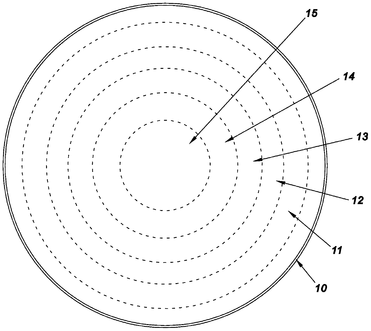
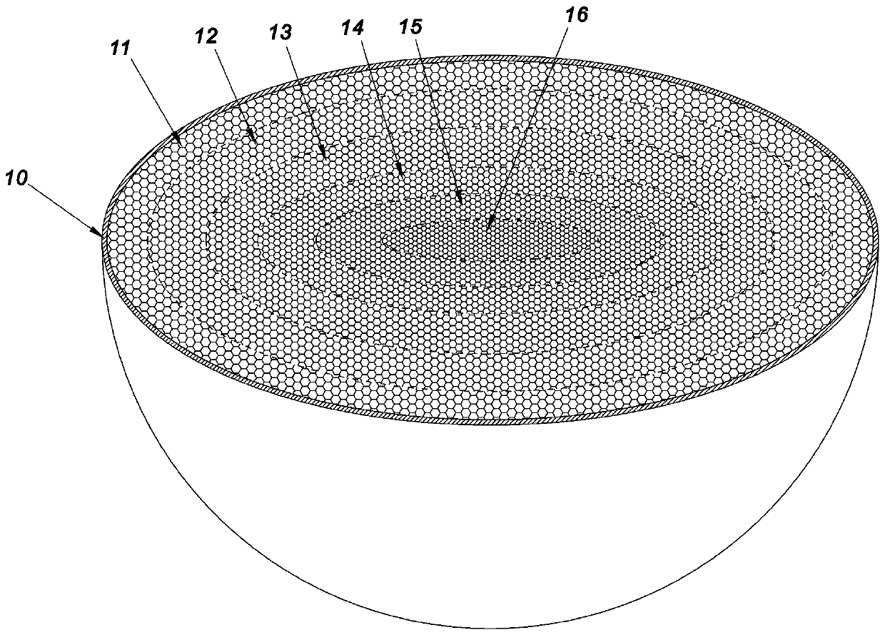
[0049] Such as figure 1 As shown, this embodiment takes the production of a spherical Lunberg lens with 5 dielectric layers as an example. Such a Luneberg lens is sequentially composed of a lens half shell 10, a first dielectric layer 11, a second dielectric layer 12, a third dielectric layer 13, a fourth dielectric layer 14, a fifth dielectric layer 15 and a half inner core 16 from outside to inside. .

[0050] Its processing method is as follows:

[0051] Step 1): Prepare a hemispherical shell as the lens half shell 10 .

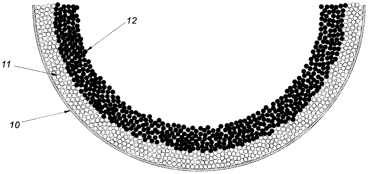
[0052] Step 2): put the lens half-shell 10 into a hemispherical die, the outer wall of the lens half-shell 10 is in contact with the hemispherical die, and this hemispherical die is used to fix the lens half-shell 10 and to bear the punch force, so as to prevent the lens half-shell 10 from being deformed by force. Spray adhesive on the inner wall surface of the lens half-shell 10, pour the prefabricated first granular material into the lens half-shell ...

Embodiment 2

[0067] In this embodiment, the production of a spheroidal Luneberg lens with 5 dielectric layers is taken as an example.

[0068] A spheroid can be understood as a three-dimensional shape formed by rotating an ellipse along its major axis, such as Figure 4 As shown, such a three-dimensional shape is a three-dimensional shape that can be separated axisymmetrically. There are two methods for axisymmetrically separating the three-dimensional shape: one is to divide the three-dimensional shape into two axisymmetric halves by the plane passing through the major axis of the ellipse , for example with Figure 4 The other is to divide the three-dimensional shape into two axisymmetric halves by a plane passing through the minor axis of the ellipse and perpendicular to the major axis, for example, Figure 4 The B plane to separate.

[0069] In the two halves obtained by the previous separation method, neither half is a rotating body. Therefore, when making a half-side Lunberg lens, t...


PUM


Abstract

The invention provides a novel production method of a Luneberg lens. A high-performance Luneberg lens with stable indicators can be manufactured under the conditions of room temperature, normal pressure and low cost. The production method comprises the following steps: a half shell is prepared as a lens half shell, an adhesive is sprayed on the inner wall surface of the lens half shell, the prefabricated first granular material is laid into the lens half shell, the first granular material is pressed by a punch to form a first dielectric layer, the adhesive is sprayed on the surface of the first dielectric layer, the second granular material is laid on the surface of the first dielectric layer and pressed and the like so that a half Luneberg lens is obtained, and then the two half Luneberglenses are bonded together to form a single Luneberg lens. The production method of the Luneberg lens has the advantages of simple production process, low production cost, low weight, easy control oflens characteristics and excellent lens performance indicators and the like.

Description

technical field [0001] The invention relates to the field of communication equipment production, more specifically, to a production method of a Lunberg lens. Background technique [0002] Luneberg lens technology, proposed by RK Luneberg in 1944 based on geometric optics, is used as an antenna and scatterer, mainly used in fast scanning systems, satellite communication systems, automotive anti-collision radars, and radar reflectors. [0003] Theoretically, the dielectric constant of the dielectric material used for Lunberg lenses should change continuously from 2 to 1 following certain mathematical laws from the center of the sphere to the outer diameter. However, such an ideal medium does not exist in nature, so in actual design, discrete spherical shells with layered design are often used instead. [0004] In order to make the actual performance of Lunberg lens close to the theoretical performance, there are already a variety of Lunberg lens production schemes, such as: ...

Claims


Application Information

Patent Timeline
Patent Type & Authority Applications(China)
IPC IPC(8): H01Q15/08
CPCH01Q15/08
Inventor 郑洪振芦永超窦英乾
Owner FOSHAN CITY EAHISON COMM
Why Eureka
Try Eureka