Annular voltage-controlled oscillator with self-biased structure

A voltage-controlled oscillator, self-biasing technology, applied in the direction of automatic power control, electrical components, etc., can solve the problems of voltage-controlled oscillator fluctuation, small output swing, phase noise difference, etc., to solve the output swing Small, increase the output swing, increase the effect of the suppression capability

Active Publication Date: 2019-07-09
NANJING UNIV OF POSTS & TELECOMM
View PDF4 Cites 2 Cited by
  • Summary
  • Abstract
  • Description
  • Claims
  • Application Information

AI Technical Summary

Problems solved by technology

[0003] The purpose of the present invention is to solve the problem that the voltage-controlled oscillator is affected by the fluctuation of the power supply voltage and the phase noise difference, and provide a ring voltage-controlled oscillator with a self-bias structure to realize the establishment of a constant current independent of the power supply voltage and increase the output swing , to solve the technical problems of poor output performance and small output swing of ring voltage-controlled oscillators affected by power supply voltage fluctuations

Method used


Image

  • Annular voltage-controlled oscillator with self-biased structure
  • Annular voltage-controlled oscillator with self-biased structure
  • Annular voltage-controlled oscillator with self-biased structure

Examples


Embodiment Construction

[0015] The technical solutions of the present invention will be further elaborated below according to the drawings and in conjunction with the embodiments.

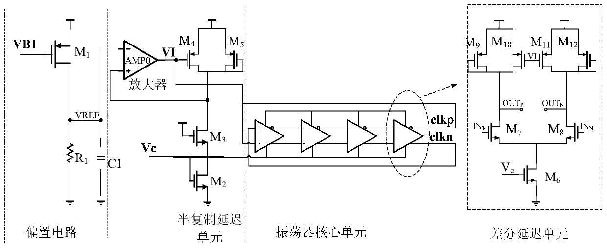
[0016] see figure 1 , the ring voltage-controlled oscillator circuit of self-bias structure of the present invention comprises self-bias unit and oscillator core unit; Self-bias unit comprises input bias circuit, operational amplifier AMP0 and semi-replication delay circuit, and oscillator core unit comprises The feedback oscillation loop formed by cascading differential delay circuits with the same multi-stage structure, the structure of the half-replication delay circuit is the same as the half-side circuit structure of the differential delay circuit; the output of the input bias circuit is provided by the differential negative input terminal ON of the operational amplifier AMP0 The reference voltage VREF, the differential positive input terminal OP of the operational amplifier AMP0 is connected to the gates of the load...


PUM


Abstract

The invention discloses an annular voltage-controlled oscillator with a self-biased structure. The annular voltage-controlled oscillator comprises a self-biased unit and an oscillator core unit, wherein the self-biased unit comprises an input biasing circuit, an operational amplifier and a half-replica delay circuit, the oscillator core unit comprises a feedback oscillation loop formed by cascading multiple stages of differential delay circuits with the same structure, and the structure of the half-replica delay circuit is the same as that of a half-side circuit of the differential delay circuit. The input biasing circuit provides a reference voltage VREF for the operational amplifier, a constant biasing voltage irrelevant to the power supply voltage is established; the output frequency ischanged by adjusting the tail current of the differential delay circuit, so that the output common-mode level is equal to the reference voltage, the problems that the working frequency of the ring oscillator fluctuates greatly along with the voltage of the power supply and the common-mode level of the core output of the oscillator is changed are solved, and the inhibition capability of the voltage-controlled oscillator on the noise of the power supply and the stable output swing are improved.

Description

technical field [0001] The invention relates to a voltage-controlled oscillator, in particular to a ring voltage-controlled oscillator with a self-bias structure. Background technique [0002] In the SOC system on a chip, it is necessary to design a phase-locked loop circuit to provide a clock frequency for the system. PLLs traditionally used in SOC systems have large power consumption, large area, and poor phase noise. The voltage-controlled oscillator is the core part of the PLL. Therefore, it is of great significance to study oscillator circuits with low power consumption, small area and good phase noise. Contents of the invention [0003] The purpose of the present invention is to solve the problem that the voltage-controlled oscillator is affected by the fluctuation of the power supply voltage and the phase noise difference, and provide a ring-shaped voltage-controlled oscillator with a self-bias structure to realize the establishment of a constant current independen...

Claims


Application Information

Patent Timeline
Patent Type & Authority Applications(China)
IPC IPC(8): H03L7/099
CPCH03L7/0995
Inventor 吉新村郭风岐沈梦琪张宪伟夏晓娟郭宇锋
Owner NANJING UNIV OF POSTS & TELECOMM
Why Eureka
Try Eureka