
Overflow valve for excavator main control valve with filter device

A filter device and main control valve technology, which is applied in the field of hydraulic devices to achieve the effects of good opening and closing characteristics, compact structure and stable internal pressure

Pending Publication Date: 2019-07-12
龙工(上海)精工液压有限公司
View PDF0 Cites 0 Cited by
  • Summary
  • Abstract
  • Description
  • Claims
  • Application Information

AI Technical Summary

Problems solved by technology

[0003] The technical problem to be solved by the present invention is: solve the problem of how to improve the cleanliness of the hydraulic oil entering the inner cavity of the valve seat

Method used


Image

  • Overflow valve for excavator main control valve with filter device
  • Overflow valve for excavator main control valve with filter device

Examples


Embodiment 1

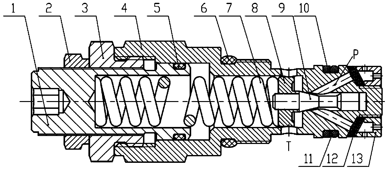
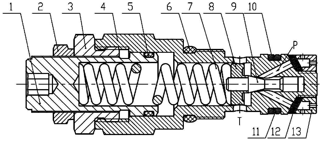
[0018] The present invention is an overflow valve for a main control valve of an excavator with a filtering device, such as figure 1 As shown, it includes a control spool 9, the control spool 9 is arranged at the front end of the inner cavity of the valve seat 4, the front end of the control spool 9 is matched with the inner cavity of the valve seat 4, and the hydraulic oil enters the control spool 9 from the matching gap to the end. The front end opens the control spool 9 after reaching the set pressure. Spring seat 8 is contained on the rear end of control spool 9, and spring force is applied on the control spool 9, and control spool 9 is closed state under normal state, and it forms line seal with valve seat 4. One end of the spring 7 withstands the rear end of the control valve core 9 through the spring seat 8, and the other end of the spring 7 withstands the front end of the adjusting bolt 1, that is, one end of the spring 7 is connected to the spring seat 8, and the othe...

Embodiment 2

[0025] In this embodiment, the valve seat 4 is provided with 4 oblique oil inlet holes P and 4 oil return inner holes T. Each inclined oil inlet P is connected with a small hole on a filter seat 13 through a filter screen 12 . Between the valve seat 4 and the filter seat 13, four layers of 60-mesh filter screens 12 are arranged. The filtering accuracy of the filter screens 12 is 25 μm, and the total thickness of all the filter screens 12 is 1.6 mm.

[0026] Others are the same as in Example 1.

Embodiment 3

[0028] In this embodiment, two layers of 60-mesh filter screens 12 are arranged between the valve seat 4 and the filter seat 13. The filtering accuracy of the filter screens 12 is 20 μm, and the total thickness of all the filter screens 12 is 0.8 mm.

[0029] Others are the same as in Example 1.


PUM


Abstract

The invention discloses an overflow valve for an excavator main control valve with a filter device. The overflow valve for the excavator main control valve with the filter device is characterized by comprising a control valve element, wherein the control valve element is arranged at the front end of an inner cavity of a valve seat; the front end of the control valve element is in clearance fit with the inner cavity of the valve seat; the rear end of the inner cavity of the valve seat is connected with the front end of an adjusting bolt in a matching way; a spring seat and a spring are arrangedin the inner cavity of the valve seat; one end of the spring presses against the rear end of the control valve element through a spring seat; the other end of the spring presses against the front endof the adjusting bolt; 4 to 6 oil inlet inclined holes and 4 to 6 oil return inner holes are formed in the valve seat and are located on the left side and the right side of the clearance fit part ofthe valve element and the valve seat; a filter seat is fixed to the head part of the valve seat; a filter screen is arranged between the filter seat and an outer end port of each oil inlet inclined hole; small holes are formed in the filter seat; and each oil inlet inclined hole is at least connected with one small hole through the corresponding filter screen. The overflow valve provided by the invention has a good on and off characteristic and the inner pressure stability, and is less influenced by the external environment factor.

Description

technical field [0001] The invention relates to a hydraulic control valve, in particular to an overflow valve for a main control valve of an excavator with a filtering device, and belongs to the technical field of hydraulic devices. Background technique [0002] The relief valve for the main control valve of the excavator is mainly used to control the maximum working pressure of the hydraulic system to protect the safety and reliability of the entire hydraulic system. According to customer feedback, the excavator often suffers from walking weakness after working for a period of time. After inspection, it is found that the pressure of the relief valve is insufficient. After investigation, it was found that: the poor working environment of the excavator and the lack of attention of the operator to maintenance often lead to the low cleanliness of the hydraulic oil, so the overflow valve is blocked by debris or burrs, and cannot be opened and closed normally, resulting in hydrau...

Claims


Application Information

Patent Timeline
Patent Type & Authority Applications(China)
IPC IPC(8): F15B13/02F15B21/041F16K17/04F16K17/06B01D35/04E02F9/22
CPCF16K17/0466F16K17/06E02F9/2225B01D35/046F15B13/024F15B21/041F15B2211/615
Inventor 郑可文马宗宇陈永耀余红波白永刚
Owner 龙工(上海)精工液压有限公司
Learn More