Industrial robot seal joint

A technology of industrial robots and joints, applied in the direction of engine seals, manipulators, mechanical equipment, etc., can solve the problems of large friction damping, reduce the layout space of seals, complicated operation, etc., to prevent the entry of foreign objects and improve the sealing stability. , the effect of reducing frictional resistance

Pending Publication Date: 2019-07-12
EFORT INTELLIGENT EQUIP CO LTD
View PDF2 Cites 7 Cited by
  • Summary
  • Abstract
  • Description
  • Claims
  • Application Information

AI Technical Summary

Problems solved by technology

[0002] In the prior art, the double seal of the robot joint usually adopts the outer V-shaped seal ring and the inner rotary shaft lip seal ring to achieve sealing. However, the arrangement of the two seals requires a large space, and the rotating seal will generate greater friction. Damping and Wear
[0003] For example, the Chinese patent number is 201710756534.0, and the patent name is a joint and industrial robot. This application adds a pressurized chamber on the basis of the existing double seal to prevent external foreign matter from entering, but the operation is complicated and the internal pressure is difficult to control.
[0004] In addition, the Chinese patent application number is 201810083480.0, and the patent name is an industrial robot wrist structure. This application relies on the oil seal and gap labyrinth sealing structure to realize the double-layer seal of the robot wrist. Although the seal can reduce the layout space of the seal, it does not , once the external oil seal is damaged, it cannot effectively prevent the intrusion of gas and liquid

Method used


Image

  • Industrial robot seal joint
  • Industrial robot seal joint
  • Industrial robot seal joint

Examples


Embodiment approach 1

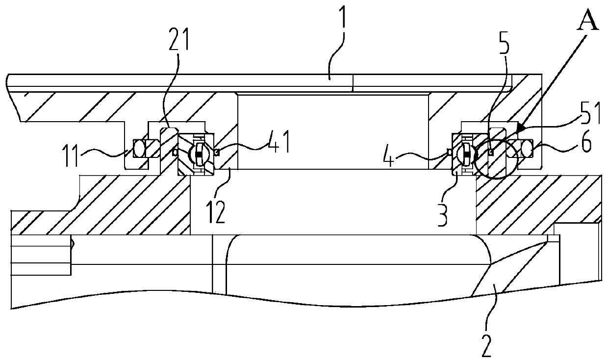
[0031] like Figure 2 to Figure 3 As shown, the outer ring of the gray ring 6 is fixed on the inner side of the outer boss 11 , and the inner ring is in contact with the outer side of the seat hole 21 . The outer ring of the gray ring 6 is fixed, and the inner ring is in rotational contact with the outer side of the seat hole 21 to form a dynamic seal.

[0032] The width of the seat hole 21 is greater than that of the self-sealing bearing 3 , and a distance of 1 mm to 2 mm is maintained between the first joint 1 and the first joint 1 . Its function is to prevent the second joint 2 from interfering with the first joint 1 when rotating.

[0033] The outer side of the inner boss 12 is provided with a first O-ring groove 4 , and the inner side of the seat hole 21 is provided with a second O-ring groove 5 .

[0034] As another improvement of this embodiment, the outer side of the inner boss 12 is provided with a first O-ring groove 4 , and the outer side of the self-sealing beari...

Embodiment approach 2

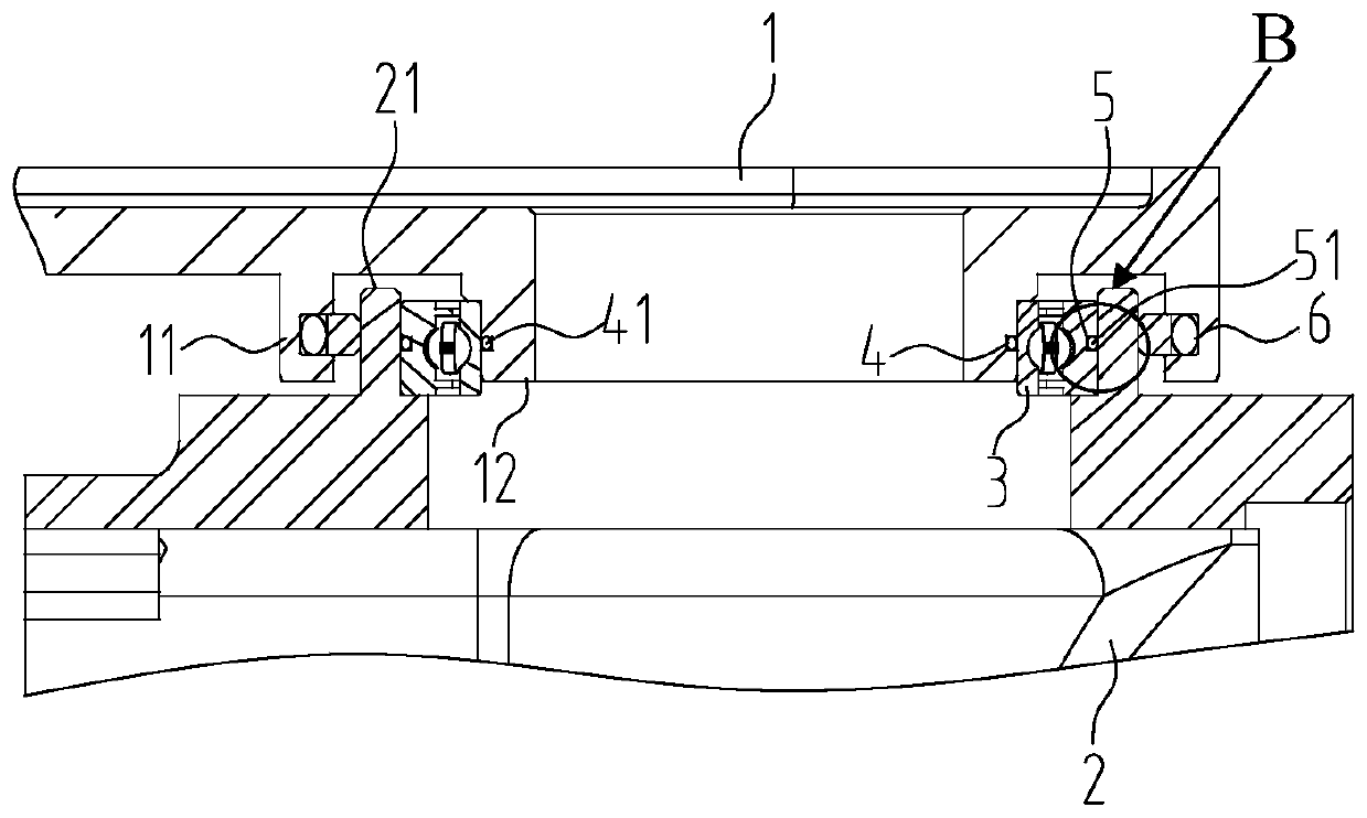
[0038] like Figure 4 As shown, the difference from Embodiment 1 is that the outer ring of the gray ring 6 is fixed inside the outer boss 11 , and the inner ring is in contact with the outer ring of the self-sealing bearing 3 . Since the surface of the outer ring of the self-sealing bearing 3 is smooth, the frictional resistance when the gray ring 6 contacts and rotates with the self-sealing bearing 3 will be reduced.

[0039] The width of the seat hole 21 is half of the width of the self-sealing bearing 3 , and a distance of 1 mm to 2 mm is kept from the first joint 1 . The self-sealing bearing 3 can be fixed on the seat hole 21 without affecting the transmission rigidity and avoiding the interference between the second joint 2 and the first joint 1 when rotating.

[0040] The outer boss 11 is stepped.

[0041] Specifically implement the installation process: First, place the first O-ring seal 41 and the second O-ring seal 51 on the first O-ring groove 4 on the outside of t...


PUM


Abstract

The invention relates to an industrial robot seal joint. The industrial robot seal joint comprises a first joint with an outer boss and an inner boss, a second joint with a base hole, and a self-sealbearing arranged between the first joint and the second joint. The second joint rotates around the axis of the first joint. A glyd ring for movable seal is arranged between the first joint and the second joint. The inner circle and the outer circle of the self-seal bearing are provided with a first O-shaped seal ring and a second O-shaped seal ring for static seal between the first joint and the second joint. A seal cavity is formed between the static seal and the movable seal. The glyd ring for the movable seal at the outer portion and the O-shaped rings arranged inside for the static seal are arranged, through combination of the glyd ring and the O-shaped rings, a double-seal structure is achieved, more compact joint seal can be achieved, friction resistance is effectively reduced, sealstability is improved, and entry of outer foreign matter is effectively prevented.

Description

technical field [0001] The invention relates to the technical field of robot equipment, in particular to an industrial robot sealing joint. Background technique [0002] In the prior art, the double seal of the robot joint usually adopts the outer V-shaped seal ring and the inner rotary shaft lip seal ring to achieve sealing. However, the arrangement of the two seals requires a large space, and the rotating seal will generate greater friction. damping and wear. [0003] For example, the Chinese patent number is 201710756534.0, and the patent name is a joint and industrial robot. This application adds a pressurized chamber to prevent external foreign matter from entering on the basis of the existing double seal. However, the operation is complicated and the internal pressure is not easy to control. [0004] In addition, the Chinese patent application number is 201810083480.0, and the patent name is an industrial robot wrist structure. This application relies on the oil seal ...

Claims


Application Information

Patent Timeline
Patent Type & Authority Applications(China)
IPC IPC(8): F16J15/06F16J15/32B25J17/02
CPCB25J17/02F16J15/06F16J15/32
Inventor 刘凯章林方俊杰陈青肖永强张帷赵从虎汪思迪
Owner EFORT INTELLIGENT EQUIP CO LTD
Why Eureka
Try Eureka