TEC(thermoelectric cooler)-free uncooled infrared focal plane array reading circuit

A focal plane array and uncooled infrared technology, which is applied in the field of uncooled infrared focal plane array, can solve the problems that the output bias point cannot be automatically determined, noise, and the blind element resistance of the pixel are not equal, etc.

Active Publication Date: 2019-07-12
北京安酷智芯科技有限公司
View PDF4 Cites 40 Cited by
  • Summary
  • Abstract
  • Description
  • Claims
  • Application Information

AI Technical Summary

Problems solved by technology

[0003] In the prior art, such as the accompanying drawings in the description figure 1 The traditional upper and lower differential current readout structure circuit shown can complete the elimination of the substrate temperature effect and signal amplification in one step, and offset correction can be performed by adjusting the bias voltage of Veb and Vfid; its main disadvantages are: 1. The front bias The noise will be directly amplified, so the bias noise is very demanding; 2. Due to the self-heating effect, the blind pixel resistance of the pixel is not equal, and the output bias point cannot be automatically determined; 3. Its circuit gain varies with the substrate temperature Larger, leading to possible loss of dynamic range at different substrate temperatures and failure of offset correction;
[0004] It can be seen that in the traditional readout circuit, due to the influence of process deviation, self-heating effect and substrate temperature, the data to be read out fluctuates greatly, and some unnecessary noise will be introduced, which seriously affects the readout quality and circuit stability

Method used


Image

  • TEC(thermoelectric cooler)-free uncooled infrared focal plane array reading circuit
  • TEC(thermoelectric cooler)-free uncooled infrared focal plane array reading circuit
  • TEC(thermoelectric cooler)-free uncooled infrared focal plane array reading circuit

Examples


Embodiment 1

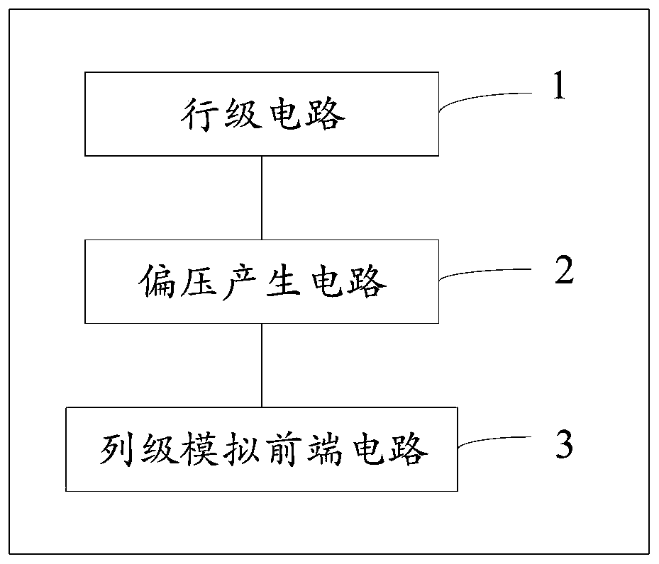
[0053] Such as figure 2 The circuit block diagram shown discloses a TEC-free uncooled infrared focal plane array readout circuit, including a bias voltage generation circuit 2, a column-level analog front-end circuit 3 and a row-level circuit 1; the bias voltage generation circuit 2 is connected to the The column-level analog front-end circuit 3 is connected to the row-level circuit 1;

[0054] The row-level circuit 1 includes a row-level image pixel and a row selection switch; the row-level circuit 1 is controlled by the row selection switch and can output a third bias voltage;

[0055] The input terminal of the bias voltage generating circuit 2 is connected to the output terminal of the row-level circuit 1, and is used to generate and output the first bias voltage and the second bias voltage together with the third bias voltage when there is a constant voltage input Voltage;

[0056] The input end of the column-level analog front-end circuit 3 is connected to the...

Embodiment 2

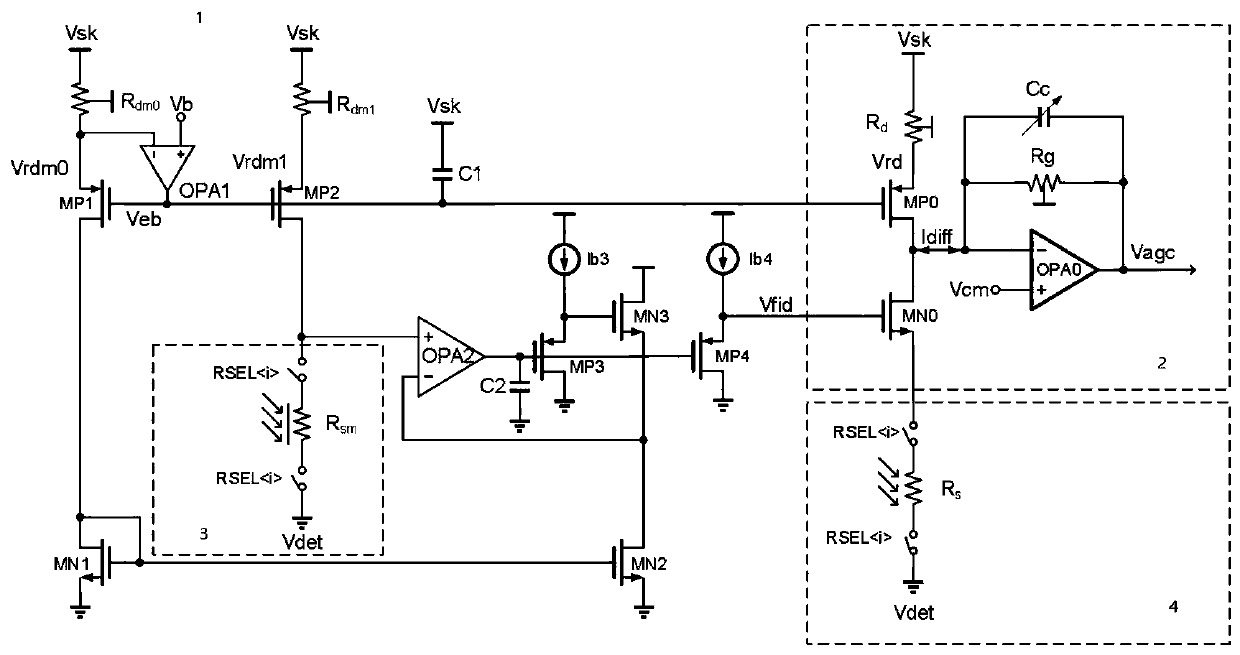
[0086] In one embodiment of the present invention, it is disclosed as image 3 The schematic diagram of the circuit structure shown; includes a bias generating circuit 1, a column-level analog front-end circuit 2, a row-level circuit 3 and a pixel-level circuit 4; wherein, the bias generating circuit 1 includes at least a first bias generating sub-circuit and a second A bias voltage generation subcircuit; the first bias voltage generation subcircuit and the second bias voltage generation subcircuit respectively output the first bias voltage and the second bias voltage;

[0087] Wherein, the first bias voltage generation sub-circuit may include a first PMOS transistor MP1, a second PMOS transistor MP2, a first NMOS transistor MN1, a second NMOS transistor MN2, a first operational amplifier OPA1, a second operational amplifier OPA2, a first mirror image Blind element R dm0 , the second mirror blind element R dm1 , decoupling capacitor C1 and power supply Vsk; it should ...

Embodiment 3

[0186] In another embodiment of the present invention, disclosed as Image 6 The schematic diagram of the circuit structure shown; includes a bias generating circuit 1, a column-level analog front-end circuit 2, a row-level circuit 3 and a pixel-level circuit 4; wherein, the bias generating circuit 1 includes at least a first bias generating sub-circuit and a second A bias voltage generation subcircuit, the first bias voltage generation subcircuit and the second bias voltage generation subcircuit respectively output the first bias voltage and the second bias voltage;

[0187] Wherein, the first bias generation sub-circuit may include a first NMOS transistor MN1, a second NMOS transistor MN2, a third NMOS transistor MN3, a fourth NMOS transistor MN4, a first operational amplifier OPA1, a second operational amplifier OPA2, a first mirror Blind element R dm0 and the second mirror blind element R dm1 ; It should be noted that the first image blind element R dm0 , the se...


PUM


Abstract

The invention discloses a TEC(thermoelectric cooler)-free uncooled infrared focal plane array reading circuit, and relates to the technical field of uncooled infrared focal plane array. A reading circuit comprises a bias generation circuit, a column-level analog front-end circuit, and a row-level circuit; the row-level circuit comprises a row-level mirror image pixel, is controlled by a row selection switch,and can output a third bias voltage; the bias generation circuit is connected with the row-level circuit, the input end of the bias generation circuit is connected with the output end of the row-level circuit; a first bias voltage and a second bias voltage are generated and outputtedbased onan inputted constant voltage and a third bias voltage; the column-level analog front-end circuitcomprises a blind pixel; the column-level analog front-end circuit is electrically connected with the bias generation circuit, the input end of the column-level analog front-end circuit is connected with the output end of the bias generation circuit to obtain two currents, and the difference between the two currents generated is amplified in a transimpedance mode and outputted as a voltage. By adopting the technical scheme of theTEC(thermoelectric cooler)-free uncooled infrared focal plane array reading circuit, the circuit has a stable output point unaffected by the substrate temperature andthe self-heating effect, and the stability of the circuit is improved.

Description

technical field [0001] The invention relates to the technical field of uncooled infrared focal plane arrays, in particular to a TEC-free uncooled infrared focal plane array readout circuit. Background technique [0002] As one of the key components of the uncooled infrared focal plane array (IRFPA), the readout circuit's main function is to preprocess the weak signals sensed by the infrared detector (such as integration, amplification, filtering, sampling / holding, etc.) and the array signal parallel / serial conversion. [0003] In the prior art, such as the accompanying drawings in the description figure 1 The traditional upper and lower differential current readout structure circuit shown can complete the elimination of the substrate temperature effect and signal amplification in one step, and offset correction can be performed by adjusting the bias voltage of Veb and Vfid; its main disadvantages are: 1. The front bias The noise will be directly amplified, so the bias nois...

Claims


Application Information

Patent Timeline
Patent Type & Authority Applications(China)
IPC IPC(8): G01J5/24
CPCG01J5/24G01J2005/202
Inventor 施薛优陈光毅
Owner 北京安酷智芯科技有限公司
Why Eureka
Try Eureka