
Automatically adjustable laser attenuator

A laser attenuation and automatic adjustment technology, applied in optics, instruments, optical components, etc., can solve problems such as laser energy fluctuations, inconvenient use, and reduced function of laser attenuators, achieving the effects of convenient use and reduced production costs

Pending Publication Date: 2019-07-12
PINGDINGSHAN UNIVERSITY
View PDF0 Cites 2 Cited by
  • Summary
  • Abstract
  • Description
  • Claims
  • Application Information

AI Technical Summary

Problems solved by technology

[0004] At present, lasers are used in many fields such as scientific research, industry, etc. During the use, the size of the laser energy needs to be adjusted, and a laser attenuator is used in the adjustment process. Most existing laser attenuators use a fixed attenuation rate, or Using non-intelligent open-loop control methods such as manually adjusting the attenuation rate, since the energy emitted by the laser will fluctuate during use, and the laser attenuator cannot adjust itself according to the situation, this will cause the energy of the laser after the laser attenuator to also fluctuate. It will fluctuate and affect the use effect of the laser
In addition, in some occasions, the laser pulse energy is relatively high, but there is no device to reduce the laser energy density in the existing laser attenuator, resulting in the laser attenuation module having to withstand a large laser energy density, and expensive high-laser energy-density resistant devices must be used. The device is easily damaged, resulting in a decrease in the function of the laser attenuator
In addition, the current laser attenuator does not have the function of adjusting the cross-sectional size of the laser beam, which is very inconvenient to use. Although laser beam expanders or beam reducers can be used, most of the existing laser beam expanders or beam reducers are fixed. Expansion rate or reduction rate, for each specific application, it is necessary to design a special beam expander or beam reducer. Such a beam expander or beam reducer has poor versatility and cannot automatically adjust the expansion rate or reduction rate, which is very inconvenient to use

Method used


Image

  • Automatically adjustable laser attenuator
  • Automatically adjustable laser attenuator
  • Automatically adjustable laser attenuator

Examples


Embodiment 1

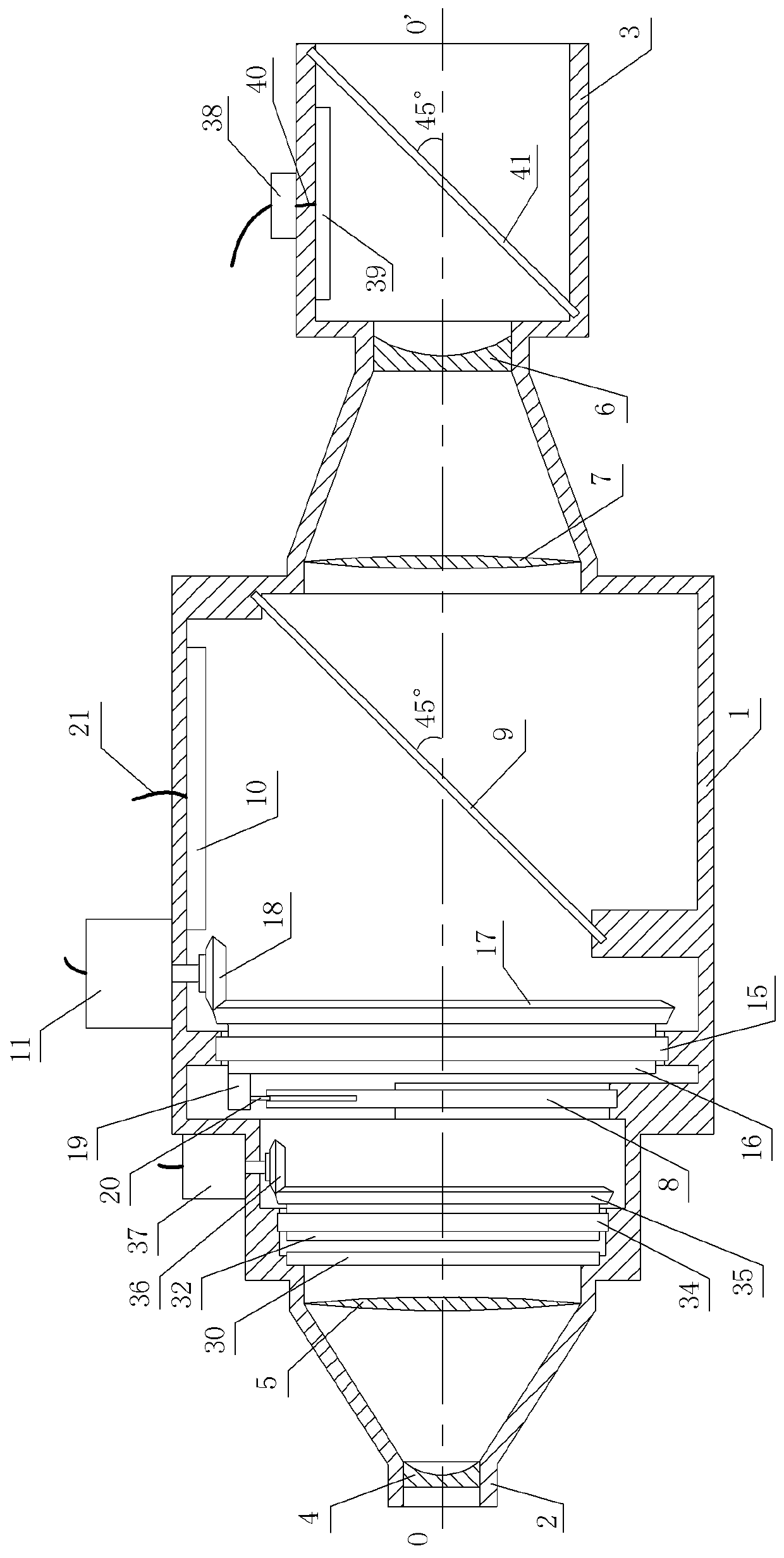
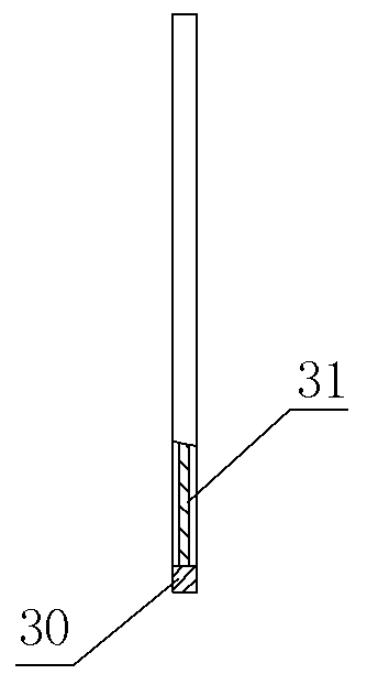
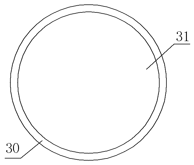
[0044] See Figure 1 ~ Figure 12 In the figure, the automatically adjustable laser attenuator contains a horizontally arranged lens barrel 1. The front end of the lens barrel 1 is the light inlet 2, and the rear end is the light outlet 3. The automatically adjustable laser attenuator also contains an entrance concave lens 4, Entrance convex lens 5, exit concave lens 6, exit convex lens 7, fixed polarizer, rotating polarizer, diaphragm 8, diaphragm adjustment mechanism, first partial reflector 9, second partial reflector 41, laser area sensor 10, laser energy meter Probe 39 and control circuit, entrance concave lens 4, entrance convex lens 5, exit concave lens 6, exit convex lens 7, fixed polarizer, rotating polarizer, diaphragm 8, diaphragm adjustment mechanism, first partial reflector 9, second partial reflector 41. The laser area sensor 10 and the laser energy meter probe 39 are both installed in the lens barrel 1. The entrance concave lens 4 is fixedly installed in the light ...

Embodiment 2

[0058] See Figure 1~Figure 11 ﹑ Figure 13 , The numbers in the figure are the same as those in the first embodiment, the meanings and working processes are also the same, the similarities are not repeated, the differences are as follows: the controller is a computer, the control circuit no longer contains the touch screen, the computer motherboard The first stepper motor motion control card and the second stepper motor motion control card are installed on the PCI slot. The output port of the first stepper motor motion control card is connected to the input port of the first stepper motor driver through a terminal board. The output port of the second stepper motor motion control card is connected to the input port of the second stepper motor driver through the terminal board; the controller, the first stepper motor driver and the second stepper motor driver are directly installed outside the lens barrel 1. .

[0059] The first stepper motor motion control card and the second st...


PUM


Abstract

The invention relates to an automatically adjustable laser attenuator including a horizontally arranged lens barrel, wherein a light-in port of the lens barrel is provided with an entrance concave lens, an entrance convex lens and an aperture in sequence, the power output end of an aperture adjustment mechanism is connected to an adjustment handle of the aperture, a fixed polarizer and a rotatingpolarizer are disposed between the entrance convex lens and the aperture, a second partial mirror, an exit concave lens and an exit convex lens are sequentially arranged in a light-out port of the lens barrel, the first partial mirror is disposed between the aperture and the exit convex lens, a laser area sensor and a laser energy meter probe are respectively located in the reflected light paths of the first and second partial mirrors; the rotation shafts of the two stepping motors in the control circuit are respectively connected to the power input ends of the aperture adjustment mechanism and the rotating polarizer, and the signal input port of the control circuit is connected to the laser area sensor and the laser energy meter probe. The automatically adjustable laser attenuator can adjust the energy and cross-sectional area of the laser beam in real time, with accurate control and high precision.

Description

[0001] (1) Technical fields: [0002] The invention relates to a laser attenuator, in particular to a laser attenuator that can be automatically adjusted. [0003] (2) Background technology: [0004] At present, lasers are used in many fields such as scientific research and industry. The laser energy needs to be adjusted during use, and laser attenuators are used in the adjustment process. The existing laser attenuators mostly use a fixed attenuation rate, or Using non-intelligent open-loop control methods such as manual adjustment of the attenuation rate, because the energy emitted by the laser fluctuates during use, and the laser attenuator cannot be adjusted according to the situation, which will cause the energy of the laser after the laser attenuator to also be Will fluctuate and affect the effect of laser use. In addition, the laser pulse energy is relatively high in some occasions, but there is no device to reduce the laser energy density in the existing laser attenuator. As ...

Claims


Application Information

Patent Timeline
Patent Type & Authority Applications(China)
IPC IPC(8): G02B27/28G02B27/09
CPCG02B27/281G02B27/0955G02B27/0988
Inventor 李阔湖宋晓燕杜豪杰杨光卫亚博赵换丽薛亚许孙现亭
Owner PINGDINGSHAN UNIVERSITY
Learn More