Display equipment detection method, device and system

A technology of display equipment and detection methods, applied in static indicators, voice analysis, instruments, etc., can solve problems such as manual detection errors and missed detections, and achieve the effect of saving time and cost and accurate detection results.

Inactive Publication Date: 2019-07-12
FREESENSE IMAGE TECH
View PDF7 Cites 0 Cited by
  • Summary
  • Abstract
  • Description
  • Claims
  • Application Information

AI Technical Summary

Problems solved by technology

[0005] In view of the above-mentioned defects of the prior art, the technical problem to be solved by the present invent

Method used


Image

  • Display equipment detection method, device and system
  • Display equipment detection method, device and system
  • Display equipment detection method, device and system

Examples


Embodiment 1

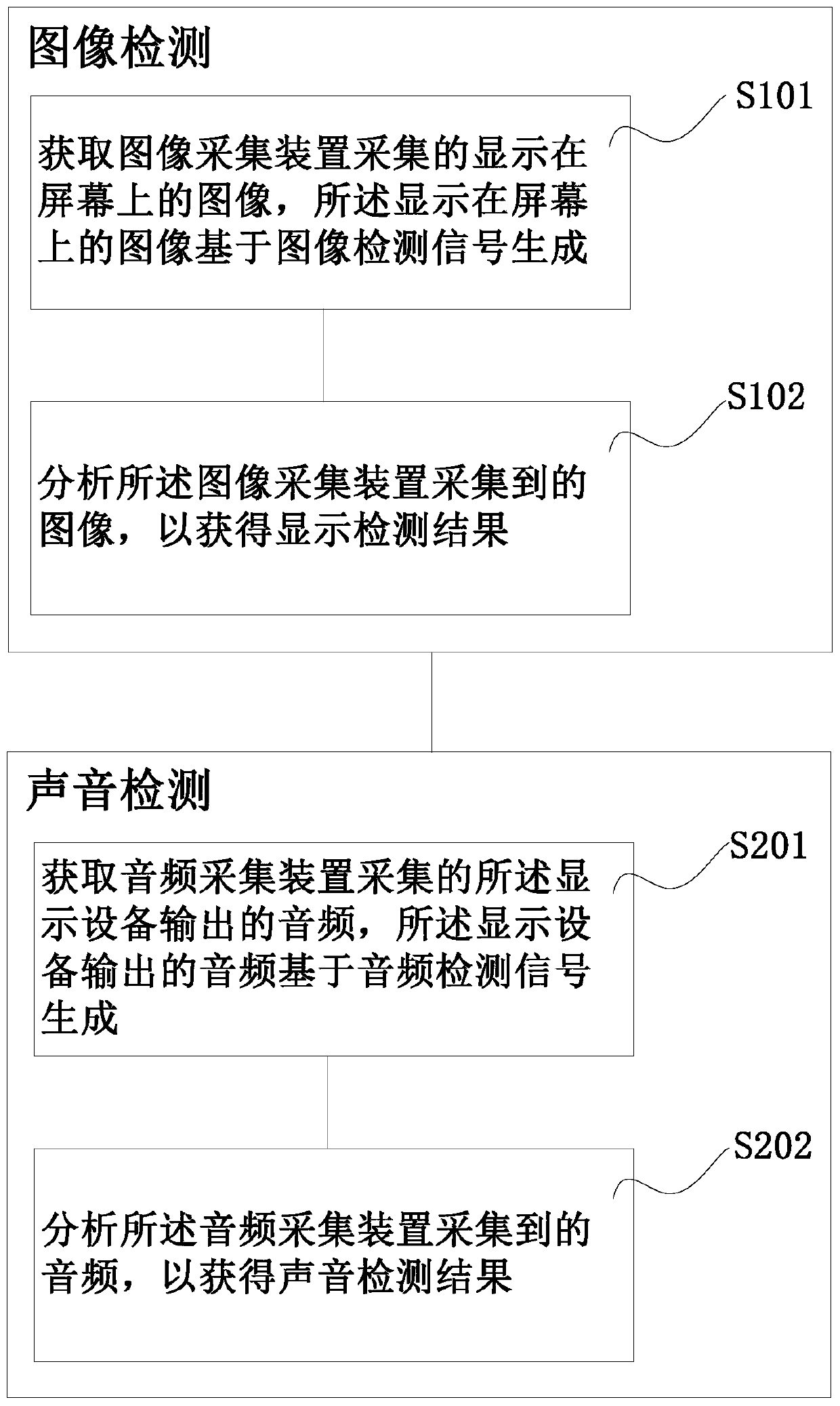
[0050] figure 1 is a schematic diagram of the detection method of the display device according to the embodiment of the present invention, such as figure 1 As shown, in the detection method of the display device in this embodiment, the display device includes a signal source interface, and the detection method of the display device includes image detection and sound detection.

[0051] For example, in this embodiment, the display device to be detected (such as a television set, a computer display screen or an advertising screen, etc.) is equipped with a plurality of signal source interfaces to be compatible with multiple signals that can be received, for example, ATV (Analog TV, input Analog) signal, AV (audio Audio and Video Video) signal, DP (DisplayPort, high-definition digital display port) signal, DTMB (DigitalTelevision Terrestrial Multimedia Broadcasting, digital TV terrestrial multimedia broadcasting) signal, DVI (Digital Visual Interface, digital video interface) Sig...

Embodiment 2

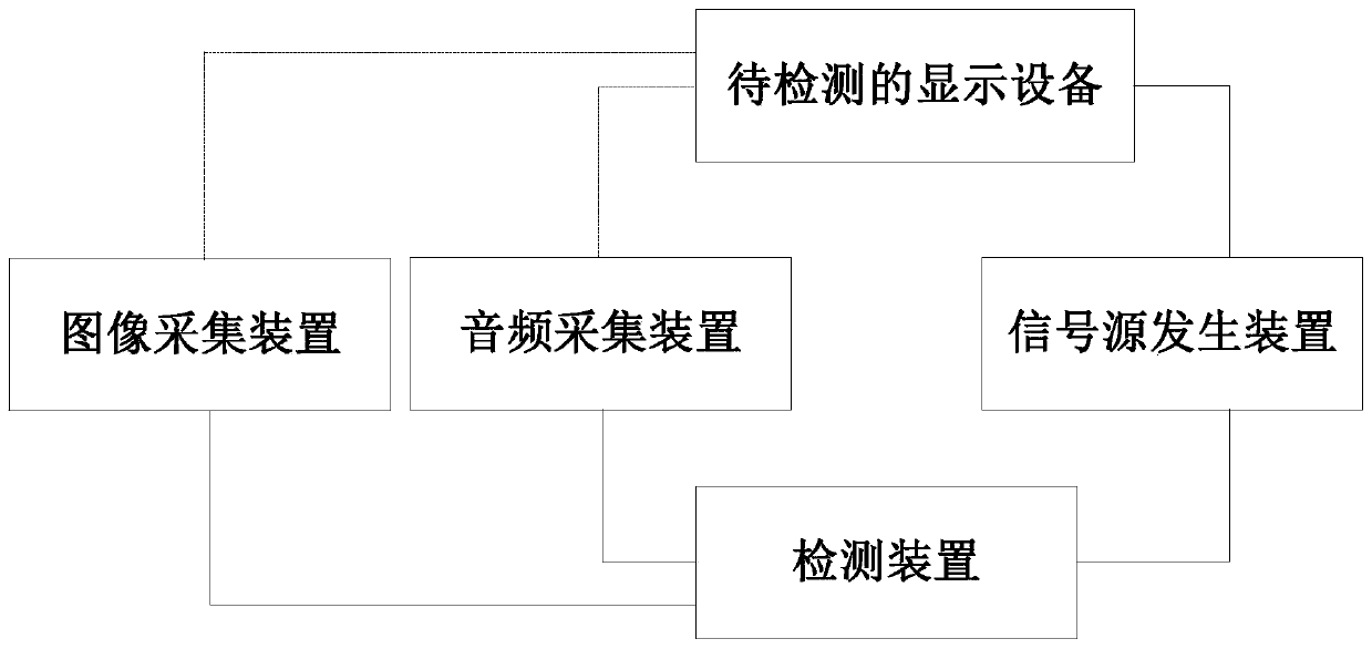
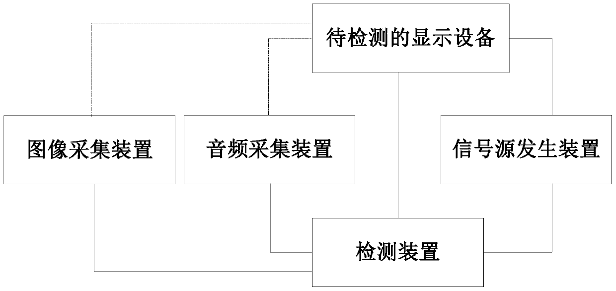
[0081] figure 2 is a schematic diagram of a detection system of a display device according to an embodiment of the present invention, such as figure 2 As shown, the inspection system of this embodiment includes a display device to be inspected, an image acquisition device, an audio acquisition device, a signal source generation device and a detection device.

[0082] Display devices to be detected, such as televisions, computer displays (LCD, liquid crystal display, etc.) For different information source signals, display detection such as image clarity, image contrast, image color, image loss, deformation, etc. and sound detection such as silence, reverse, light tone, sound interruption, and sound vibration, etc., wherein each display Multiple signal source interfaces will be installed on the device to be compatible with receiving multiple signal sources, for example, at least one of ATV signal, AV signal, DP signal, DTMB signal, DVI signal, HDMI signal, MHL signal, VGA sig...


PUM


Abstract

The invention discloses a display equipment detection method, device and system, the display equipment comprises a signal source interface, and the detection method comprises image detection and sounddetection; the image detection comprises the following steps: acquiring an image displayed on a screen collected by an image collection device, wherein the image displayed on the screen is generatedbased on an image detection signal; analyzing the image acquired by the image acquisition device to obtain a display detection result; the sound detection comprises the following steps: obtaining an audio output by the display equipment and collected by an audio collection device, wherein the audio output by the display equipment is generated based on an audio detection signal; analyzing the audiocollected by the audio collection device to obtain a sound detection result; wherein the image detection signal and the audio detection signal are respectively input into the signal source interface,or the image detection signal and the audio detection signal are contained in a video detection signal input into the signal source interface.

Description

technical field [0001] The invention relates to the field of equipment detection, in particular to a detection method, device and system for a display device. Background technique [0002] Display devices are used to display various information, and are widely used in office, teaching, entertainment, business presentations, etc. Existing display devices include Cathode Ray Tube (CRT) displays, Liquid Crystal Displays (LCD), Light Emitting Diode (LED) displays, Plasma Displays (PDP) and other types. [0003] However, the existing display devices can not only display images on the screen, but also play sounds at the same time, and the types of signal sources input to the display devices are increasing day by day. For example, LCD screen display devices such as TVs can receive various image signals, audio signals Or a signal source such as a video signal. When the display device has been assembled, the quality inspection before leaving the factory is generally carried out by ...

Claims


Application Information

Patent Timeline
IPC IPC(8): G09G3/00G10L25/51
CPCG09G3/006G10L25/51
Inventor 王敏
Owner FREESENSE IMAGE TECH
Why Eureka
Try Eureka