Slag removing machine for sword grid

The technology of a slag remover and a sword fence is applied in the field of slag removal, which can solve the problems of low slag removal efficiency and low degree of automation, and achieve the effects of reducing the labor intensity of operation, reducing labor intensity, and being easy to control.

Pending Publication Date: 2019-07-16
成都大地机械设备制造有限公司
View PDF0 Cites 4 Cited by
  • Summary
  • Abstract
  • Description
  • Claims
  • Application Information

AI Technical Summary

Problems solved by technology

[0007] For this reason, the embodiment of the present invention provides a sword grid slag remover to solve the problems of low automation and low slag removal efficiency of the existing slag remover

Method used


Image

  • Slag removing machine for sword grid
  • Slag removing machine for sword grid
  • Slag removing machine for sword grid

Examples


Embodiment 1

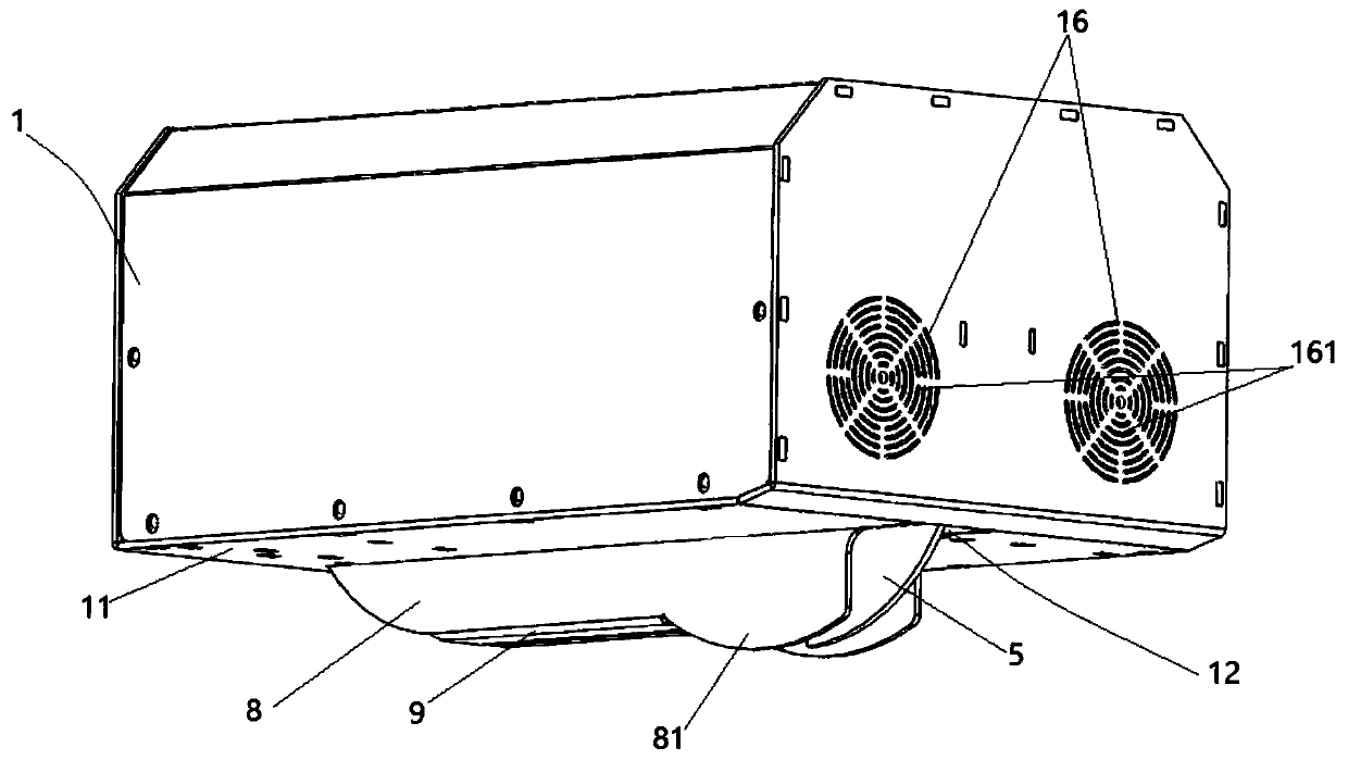
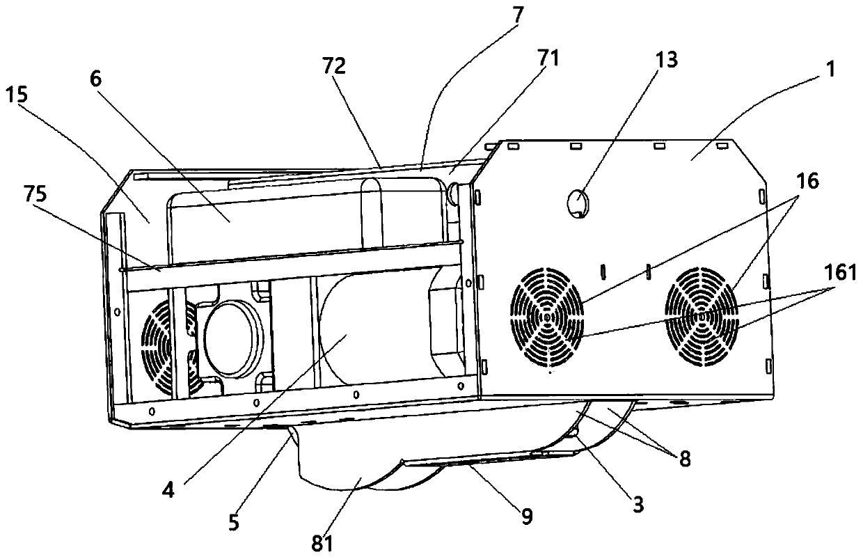
[0050] see Figure 1-7 , a sword grid slag removal machine provided by the present invention, the slag removal machine includes: a casing 1, which is a horizontally placed box, and a middle part of the bottom plate 11 of the casing 1 is opened along the running direction of the slag removal machine. The bar-shaped opening 12 corresponding to the sword rack (not shown), the width of the bar-shaped opening 12 is greater than the width of the sword rack, and the upper surface of the casing 1 is provided with a control opening (not shown), so There is a power supply opening 13 on the upper part of the side wall of the casing 1; the driving motor 2 is installed on the inner surface of the bottom plate 11 on the side of the strip opening 12, and the driving shaft 21 of the driving motor 2 extends to the corresponding slag removal machine. Above the strip-shaped opening 12 at the rear end of the direction; the driving gear 3 is vertically arranged and rotatably sleeved on the drive s...

Embodiment 2

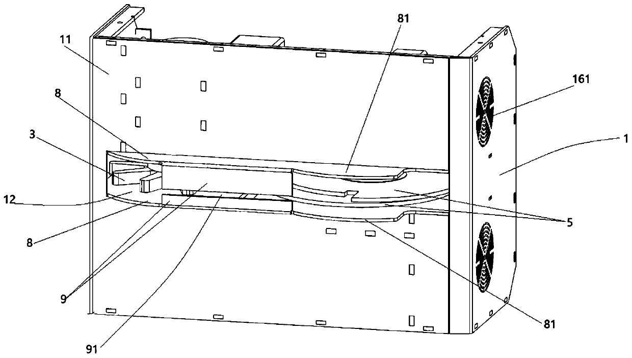
[0070] The outer surface of the bottom plate 11 of the casing 1 located on both sides of the strip opening 12 is respectively protruded with a baffle 8 along the direction vertical to the bottom plate 11; the two baffles 8 are arranged along the running direction of the slag remover; One end close to the slag removal blades 5 protrudes outward to form a guard portion 81, and the two guard portions 81 cooperate to form protection for the two slag removal blades 5; the outer edge of the guard portion 81 of the baffle plate 8 is arc-shaped.

[0071] The distance between the protective parts 81 of the two baffles 8 is slightly larger than that of the two slag removal blades 5, and they are located outside the two slag removal blades 5. The slag removal blades 5 are wrapped inside by the protective parts 81 of the two baffle plates 8 during operation to protect the slag removal blades. The blade 5 is not damaged by other foreign objects, prolongs the service life of the slag removal...

Embodiment 3

[0074] The width direction of the two baffle plates 8 is connected to a guide plate 9 away from the ends of the bottom plate 11 respectively. The guide plate 9 is arranged vertically to the baffle plate 8. The guide plate 9 extends to the top of the strip opening 12 away from the end of the baffle plate 8. The guide plate 9 and the baffle plate 8 cooperate to form an L-shaped structure; a guide channel 91 is formed between the two guide plates 9, and the width of the guide channel 91 is greater than the width of the sword grid rack. The guide channel 91 cooperates with the driving gear 3 to form a A guide running along the length of the bar.

[0075] The guide channel 91 formed by the cooperation of the two guide plates 9 can ensure that the two slag removal blades 5 of the slag remover just fit the two side walls of the sword grid rack for slag removal operation, thereby ensuring the stability of the slag remover operation and ensuring efficient removal. scum.

[0076] All t...


PUM

PropertyMeasurementUnit
Thicknessaaaaaaaaaa

Abstract

The embodiment of the invention discloses a slag removing machine for a sword grid. The slag removing machine comprises a machine enclosure, a driving motor, a driving gear, a slag removing motor, twoslag removing blades, a control box, and a control panel, wherein a strip-type opening is formed in a baseplate of the machine enclosure; a control opening is formed in the upper surface of the machine enclosure; a power supply opening is formed in the side wall of the machine enclosure; the driving motor is arranged on the inner surface of the baseplate; the driving gear is arranged on a drivingshaft in a sleeving manner and is engaged with the tooth surface of a sword grid rack; the slag removing motor is arranged on the inner surface of the baseplate; axle holes are respectively formed inthe two slag removing blades; the two slag removing blades are arranged on an output shaft in a sleeving manner and respectively correspond to the two side walls of the sword grid rack; the control box is arranged at the upper part of the inner side of the machine enclosure and is electrically connected to an external power source through the power supply opening; and the control panel is arranged at the control opening and is in communication connection with the control box. The slag removing machine has low cost, high work efficiency and a relatively reasonable slag removal mode and is easyand simple to handle.

Description

technical field [0001] The invention belongs to the technical field of slag removal, and in particular relates to a sword gate slag remover. Background technique [0002] As the advantages of metal laser cutting machines in sheet metal production are gradually being valued by people, laser cutting machine manufacturers devote all their energy to the upgrading of the main body, but rarely care about the supporting auxiliary tools. [0003] When the laser cutting machine is working, a large amount of high-temperature slag will be generated. The slag splashes and sticks to the sword bars on the work surface, gradually affecting the cutting quality. The traditional solution is to beat the chisel by hand, which is labor-intensive and low in efficiency. , long downtime. [0004] The slag removal machine currently on the market is a slag removal equipment produced for this problem. It adopts the principle of multi-blade longitudinal reciprocating scraping. The slag is scraped into...

Claims


Application Information

Patent Timeline
IPC IPC(8): B23K26/16
CPCB23K26/16
Inventor 陈印
Owner 成都大地机械设备制造有限公司
Why Eureka
Try Eureka