Multiaxial robot stacking workstation with positioning function

A multi-axis and robotic technology, applied in the field of palletizing workstations, can solve problems such as low work efficiency, small work range, and small number of arms, and achieve the effect of high work efficiency and wide work range

Inactive Publication Date: 2019-07-16
YELLOW RIVER CONSERVANCY TECHN INST
View PDF5 Cites 2 Cited by
  • Summary
  • Abstract
  • Description
  • Claims
  • Application Information

AI Technical Summary

Problems solved by technology

[0007] Aiming at the deficiencies of the prior art, the present invention provides a multi-axial robot palletizing workstation with positioning function, which solves the problem of traditional palletizing workstations due to the small number of arms, few axial directions, small working range, and the problem of palletizing workstations. No positioning function, low work efficiency

Method used


Image

  • Multiaxial robot stacking workstation with positioning function
  • Multiaxial robot stacking workstation with positioning function
  • Multiaxial robot stacking workstation with positioning function

Examples


Embodiment 1

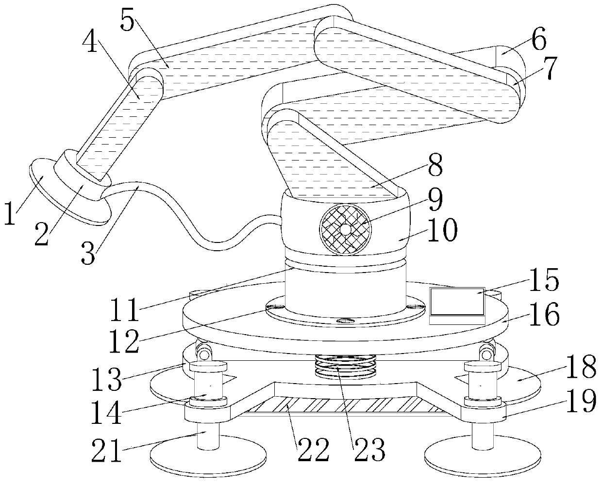
[0033] Such as Figure 1-7As shown, the present invention provides a multi-axial robot palletizing workstation with a positioning function, including a base 13 and a motor housing 11, four extension frames 19 that are symmetrically distributed in the center are welded to the edge of the base 13, and the extension frames 19 A hydraulic cylinder 14 is installed on the top, and a crawler machine 22 is installed on the bottom of the base 13, and the crawler machine 22 and the base 13 are connected by a connecting frame 37 arranged on the top of the crawler machine 22. Spring 23, the top of spring 23 is equipped with receiving platform 16, and the bottom of spring 23 is welded with base 13, and the top abuts with receiving platform 16, and the bottom of receiving platform 16 is equipped with first support 29 and second support 31, and The first support 29 and the second support 31 are arranged crosswise, the top of the receiving platform 16 is equipped with a controller 15, the ins...

Embodiment 2

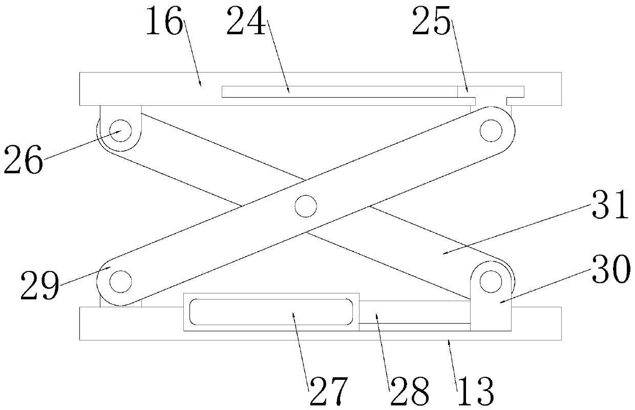
[0036] In a preferred embodiment, the motor housing 11 is connected to the receiving platform 16 by the screws 12 arranged at the bottom of the motor housing 11, and the top and bottom of the first bracket 29 and the second bracket 31 are equipped with connectors 30, and the first bracket 29 and the second bracket 31 are connected with the connecting member 30 through the pin shaft 26 arranged on the side of the connecting member 30 . The central positions of the first support 29 and the second support 31 are connected by the pin shaft 26 arranged in the central area of ​​the first support 29, and the tops of the first support 29 and the second support 31 are connected with the receiving platform 16 by a connecting piece 30, the first Bottoms of the bracket 29 and the second bracket 31 are connected to the base 13 through a connecting piece 30 .

Embodiment 3

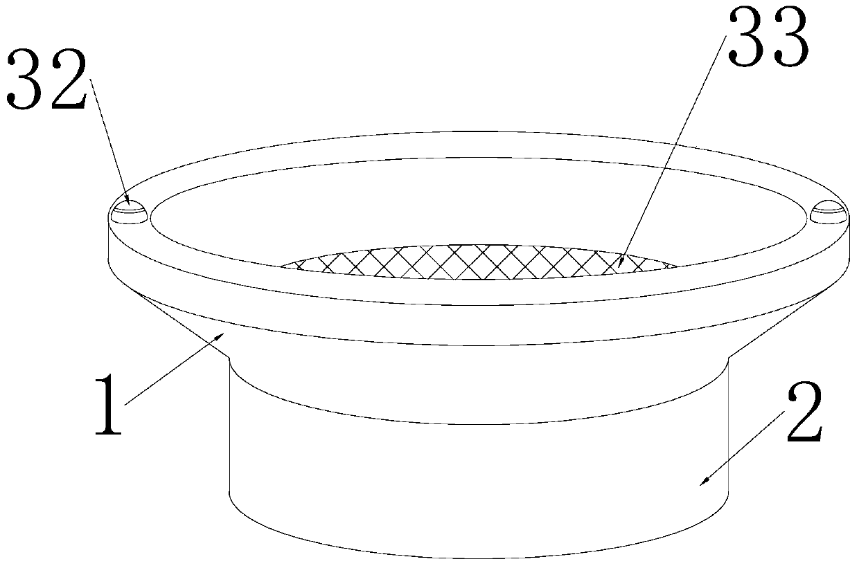
[0038] In a preferred embodiment, a slider 25 is welded to the top of the top connector 30 of the first bracket 29 , and the slider 25 is embedded in the slide groove 24 inside the receiving platform 16 and fits with the inner wall of the receiving platform 16 in clearance. The bottom of the second bracket 31 bottom connector 30 is welded with a telescopic tube 28, and one end of the telescopic tube 28 is equipped with a cylinder 27, and the cylinder 27 is embedded in the base 13, and the inside of the fan housing 10 is equipped with a fan 36, cylinder 27, hydraulic pressure The cylinder 14 , the infrared sensor 32 , the second motor 17 , the fan 36 , the first motor 35 and the crawler 22 are all electrically connected to the controller 15 . According to the height position of the transported object, the height of the receiving platform 16 can be adjusted. The adjustment process is that the cylinder 27 works, and the connecting piece 30 at the bottom of the second support 31 is...


PUM


Abstract

The invention discloses a multiaxial robot stacking workstation with a positioning function. The multiaxial robot stacking workstation with the positioning function comprises a base and a motor shell;four extension frames distributed in a central symmetry mode are welded to the edge of the base, and hydraulic cylinders are installed on the tops of the extension frames; a caterpillar machine is installed at the bottom of the base and connected with the base through a connecting frame arranged on the top of the caterpillar machine; and two springs distributed in a central symmetry mode are installed on the top of the base, a bearing platform is installed on the tops of the springs, the bottom ends of the springs are welded to the base, the top ends of the springs abut against the bearing platform, and a first bracket and a second bracket are installed at the bottom of the bearing platform. According to the multiaxial robot stacking workstation with the positioning function, a third armrod, a first arm rod, second arm rods, a supporting arm rod, a controller, second motors and infrared sensors are arranged, the problems that due to the fact that the arm rod quantity of a traditionalstacking workstation is small, the axial directions are few, the working range is narrow, the stacking workstation does not have a positioning function, and the working efficiency is low are solved.

Description

technical field [0001] The invention relates to the technical field of palletizing workstations, in particular to a multi-axis robot palletizing workstation with positioning functions. Background technique [0002] The palletizing workstation is the product of the organic combination of machinery and computer programs, which provides higher production efficiency for modern production. The palletizing machine is widely used in the palletizing industry. The system adopts the patented coordinate robot and the installation space is flexible. Compact, the idea of ​​building a high-efficiency and energy-saving fully automatic block forming machine production line within a small footprint has become a reality. With the continuous development of my country's economy and the rapid advancement of science and technology, the palletizing workstation has been used for gluing, Spot welding, arc welding, spraying, handling, measurement and other industries have a wide range of applications. ...

Claims


Application Information

Patent Timeline
Patent Type & Authority Applications(China)
IPC IPC(8): B25J19/02B25J9/16B25J15/06B25J9/02B25J19/00B62D55/06
CPCB25J9/02B25J9/16B25J9/1694B25J15/0616B25J19/00B25J19/021B62D55/06
Inventor 贾磊牛聪王艳凤王瑨何昕
Owner YELLOW RIVER CONSERVANCY TECHN INST
Why Eureka
Try Eureka