Electro-hydraulic joint control rapid response type high-pressure common rail oil injector

A fast-response, high-pressure common rail technology, used in machines/engines, fuel injection devices, engine components, etc., can solve the problems of not meeting the matching requirements of high-efficiency and energy-saving diesel engines, reducing opening and closing times, and reducing volume and weight. Achieve the effect of improving work stability and reliability, reducing movement fluctuations, and reducing intermediate transmission parts

Pending Publication Date: 2019-07-16
无锡格林鲍尔科技有限公司 +1
View PDF0 Cites 1 Cited by
  • Summary
  • Abstract
  • Description
  • Claims
  • Application Information

AI Technical Summary

Problems solved by technology

[0008] The existing high-pressure common rail injector adopts long valve stem transmission, which is slow in response and complex in structure. It cannot reduce the opening time and closing time at the same time. The power density is small, and there is room for reduction in volume and weight. Therefore, it is necessary to improve the design of the existing high-pressure common rail injector

Method used


Image

  • Electro-hydraulic joint control rapid response type high-pressure common rail oil injector
  • Electro-hydraulic joint control rapid response type high-pressure common rail oil injector
  • Electro-hydraulic joint control rapid response type high-pressure common rail oil injector

Examples


Embodiment 1

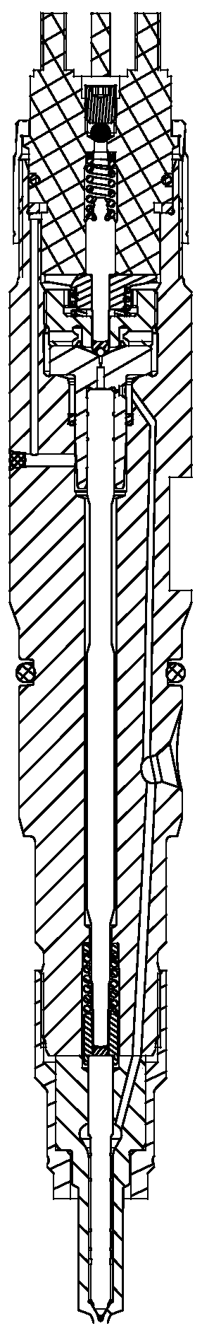
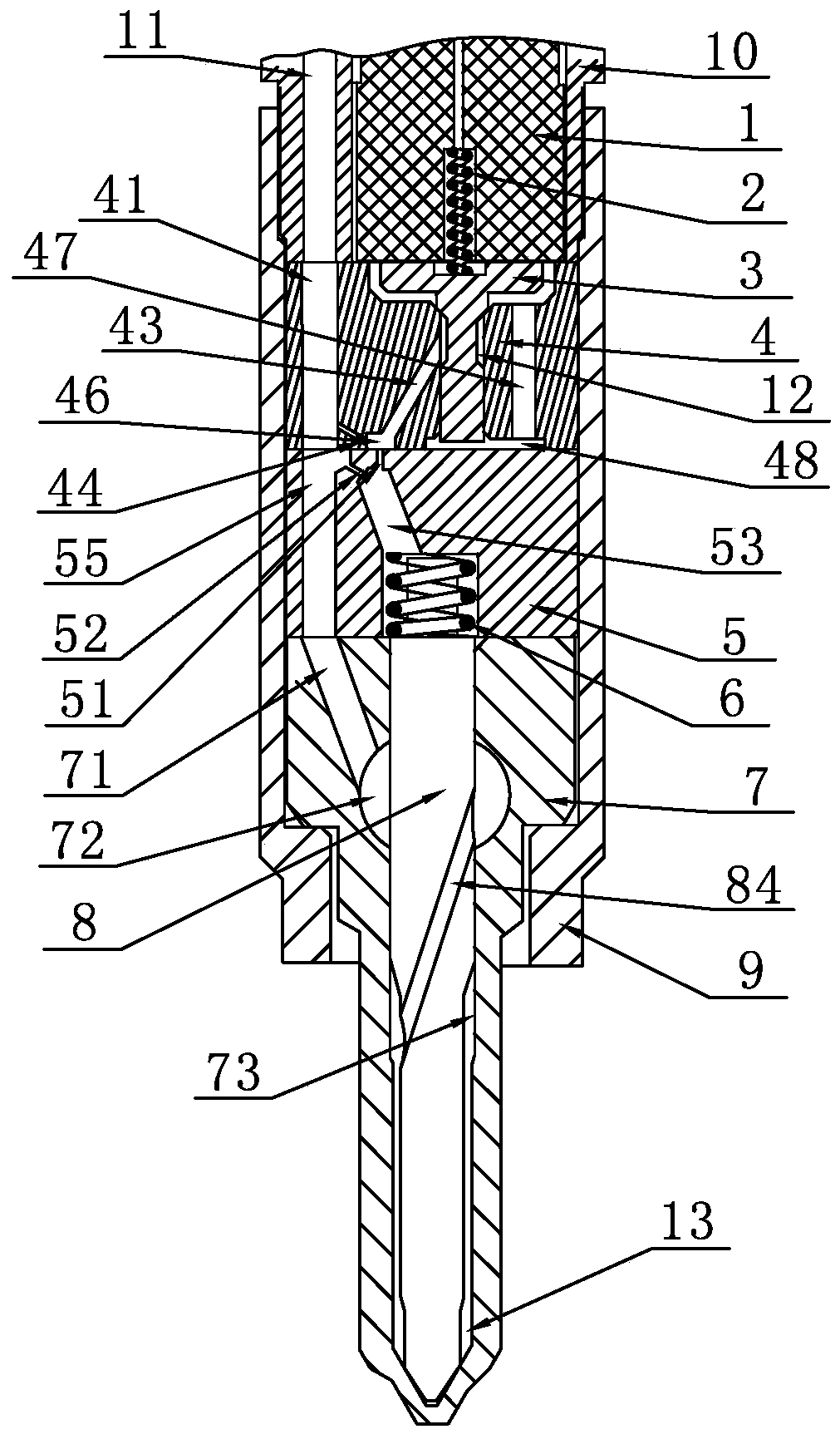
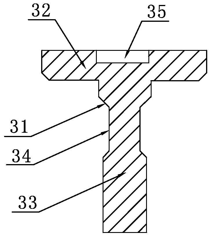
[0034] Embodiment 1: An electro-hydraulic joint control fast response type high-pressure common rail injector, such as Figure 2-Figure 6As shown, it includes electromagnetic actuator 1, upper spring 2, armature 3, armature seat 4, valve seat 5, lower spring 6, oil nozzle valve body 7, oil nozzle needle valve 8, tight cap 9 and injector body 10. The armature 3 is provided with a sealing cone 31, an iron absorber 32, a guide post 33, an oil holding groove 34 and a spring seat hole 35, the sealing cone 31 is arranged between the iron absorbing body 32 and the guide post 33, and the oil holding groove 34 is arranged On the guide column 33, and located below the sealing cone surface 31, the spring seat hole 35 is arranged at the center of the top surface of the magnet body 32; Channel 43, upper throttle hole 44, guide hole 45, lower oil inlet cavity 46, oil return hole 47, oil return cavity 48 and armature seat hole 49, taper hole surface 42 is coaxially set with guide hole 45, an...

Embodiment 2

[0042] Embodiment 2: The difference from Embodiment 1 is that: the cylindrical surface oil inlet grooves 84 are distributed along the axial line on the cylindrical surface between the guide section 81 and the execution section 83 .


PUM


Abstract

The invention discloses an electro-hydraulic joint control rapid response type high-pressure common rail oil injector. The electro-hydraulic joint control rapid response type high-pressure common railoil injector comprises an electromagnetic actuator, an upper spring, an armature, an armature seat, a valve seat, a lower spring, an oil nozzle valve body, an oil nozzle needle valve, a tightening cap and an oil injector body; a unique oil inlet and outlet path is formed between the armature, the armature seat and the valve seat, the pressure in a high-pressure channel is regulated through throttling holes with different flow rates, the electromagnetic actuator and the hydraulic thrust principle are adopted to realize the rapid opening and closing of an oil nozzle, the opening time and the closing time can be simultaneously reduced, the rigid long valve rod transmission is cancelled, the response speed is high, the power density is high, the size and the weight are smaller than that of the prior art, the structure is ingenious, the matching requirements of the high-efficiency energy-saving diesel engine can be met, and the operation reliability and the stability of the high-pressure common rail oil injector are improved.

Description

[0001] Technical field: [0002] The patent of the present invention relates to an electronically controlled common rail fuel injector for diesel engines. [0003] Background technique: [0004] During the working process of the common rail injector assembly of the engine, it takes a certain delay time from when the injector receives the injection pulse signal to when the injector realizes pressure oil injection. This delay time is called the opening delay time ; And from the injector receiving the injection closing pulse signal to the realization of the injection closing also needs to experience a certain delay time, this delay time is called the closing delay time; for the injector, the shorter the opening delay and closing delay time , indicating that the faster the response of the injector, the faster the response of the injector, the more conducive to the stability of the injector, the improvement of the engine speed adapted to the injector assembly, and the improvement of...

Claims


Application Information

Patent Timeline
Patent Type & Authority Applications(China)
IPC IPC(8): F02M47/02F02M61/10F02M63/00
CPCF02M47/027F02M61/10F02M63/0021
Inventor 吴小勇刘义亭庄福如沙有胜鞠得雨王进李明钱音瑶赵波
Owner 无锡格林鲍尔科技有限公司
Why Eureka
Try Eureka