Check patentability & draft patents in minutes with Patsnap Eureka AI!

Optical sensor

A technology of optical sensor and light source, applied in the field of optical sensor, can solve problems such as wrong measurement and interference fluorescence measurement

Inactive Publication Date: 2019-07-16
ENDRESSHAUSER CONDUCTA GMBHCO
View PDF13 Cites 0 Cited by
  • Summary
  • Abstract
  • Description
  • Claims
  • Application Information

AI Technical Summary

Problems solved by technology

This scattered transmitted light can also enter the receiver 3 and interfere with the measurement of fluorescence and lead to erroneous measurements

Method used


Image

  • Optical sensor
  • Optical sensor
  • Optical sensor

Examples


Embodiment Construction

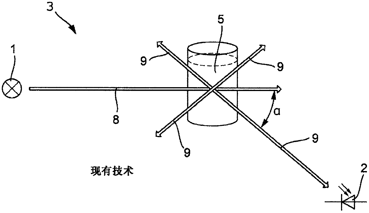
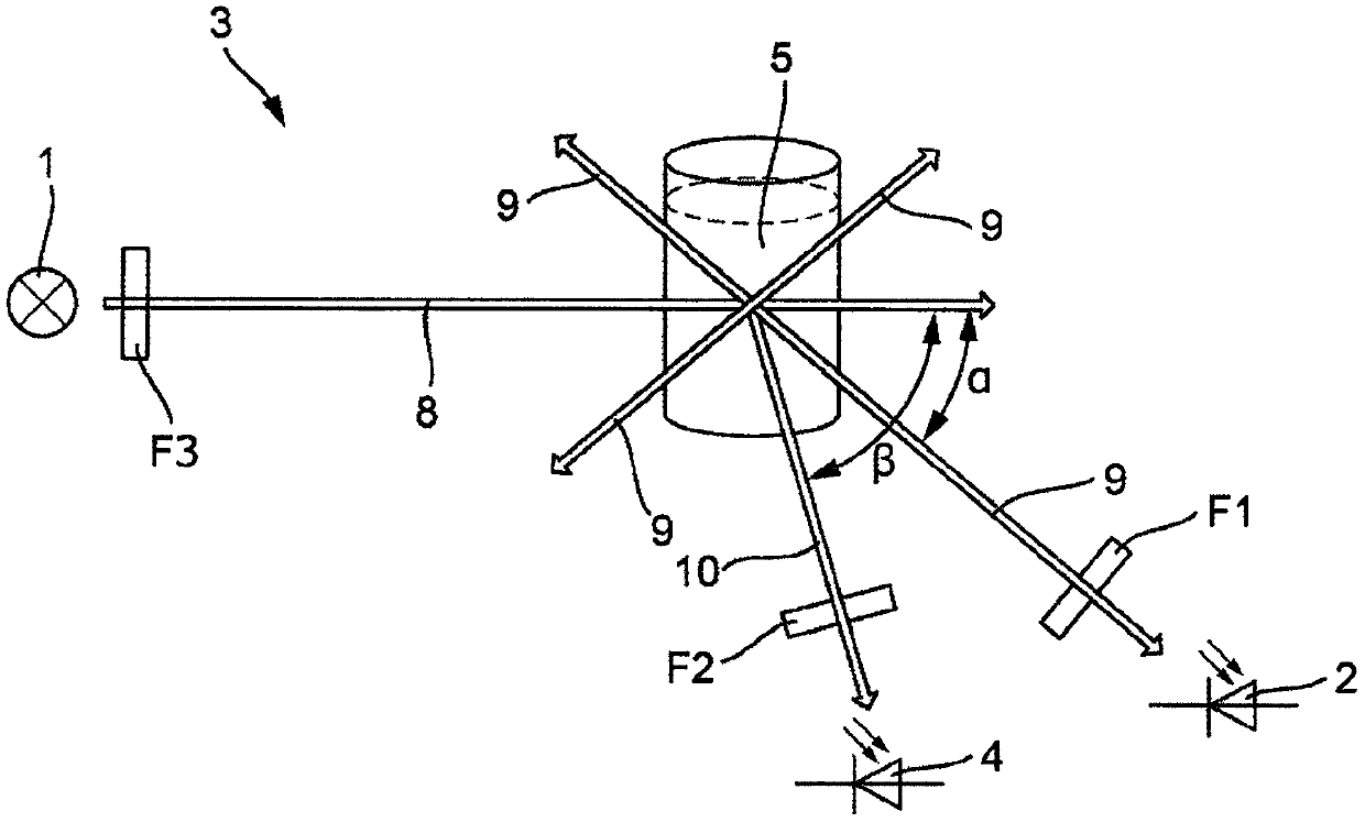
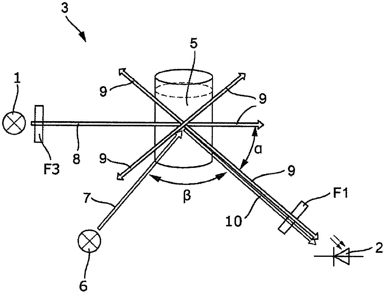
[0029] In the following, only the differences from the prior art described above are discussed. The claimed sensor as a whole bears the reference numeral 3 and is located at figure 2 is shown schematically. The sensor 3 is basically suitable for determining the oil-in-water content of the medium 5 .

[0030] A light source 1 emits transmitted light 8 towards a medium 5 . The light source is a UV light source which emits light having a wavelength of 200-400 nm. For example, the light source 1 is designed as a UV flash lamp. The light source 1 can also be designed as an LED.

[0031] UV flash lamps have a spectral range from UV to IR. In the beam path after the light source, the device includes a filter F3, which suppresses the visible part of the light. Flash 1 then emits only UV and IR with filter F3, not VIS.

[0032] The transmitted light 8 is partially converted into fluorescent light 9 in the medium 5 by a fluorescent reaction. The fluorescent light 9 follows a pa...


PUM

PropertyMeasurementUnit
angleaaaaaaaaaa
diameteraaaaaaaaaa

Abstract

The present disclosure relates to an optical sensor (3) comprising at least one light source (1, 6) for emitting transmission light (8, 7) into a medium (5), at least one detector (2, 4), wherein thetransmission light (8, 7) is at least partially converted in the medium (5) by fluorescence into fluorescent light (9) and the detector (2) receives the fluorescent light (9), wherein a first receiversignal can be generated from the fluorescent light (8, 7), and wherein a first measured value can be determined from the first receiver signal, wherein the transmission light (8, 7) is at least partially scattered by means of the medium (5) to form scattered light (10), and the detector (4) receives the scattered light (10), wherein a second receiver signal can be generated from the scattered light, and wherein a second measured value can be determined from the second receiver signal. The present disclosure further relates to a method for determining a first and second measured value of a medium.

Description

technical field [0001] The invention relates to an optical sensor designed for determining a measured value of a measured variable in process automation technology in a medium. Background technique [0002] For example, the sensor is a fluorescent sensor. To measure fluorescence, the medium is typically illuminated with short-wavelength excitation light and the longer-wavelength fluorescence produced by the medium is detected. Such as figure 1 Fluorescence measurements are typically arranged as shown. [0003] The fluorescence sensor 3 includes a light source 1 and a receiver 2 . The light source 1 emits transmitted light; the receiver receives received light. Since the fluorescence radiates in all spatial directions, the beam paths of the emitted and received light can in principle form any angle α to one another. [0004] Fluorescent and non-fluorescent particles scatter transmitted light. This scattered transmitted light can also enter the receiver 3 and interfere w...

Claims


Application Information

Patent Timeline
Patent Type & Authority Applications(China)
IPC IPC(8): G01N21/49G01N21/64
CPCG01N21/49G01N21/64G01N21/51G01N33/1833G01N2021/6465
Inventor 拉尔夫·伯恩哈特德特勒夫·维特默
Owner ENDRESSHAUSER CONDUCTA GMBHCO
Features
  • R&D
  • Intellectual Property
  • Life Sciences
  • Materials
  • Tech Scout
  • Unparalleled Data Quality
  • Higher Quality Content
  • 60% Fewer Hallucinations
Learn More